

Views: 16 Author: Site Editor Publish Time: 2026-03-11 Origin: Site


ASME (American Society of Mechanical Engineers) B16 series standards are critical technical specifications in industrial piping systems. They cover comprehensive requirements for pipe components—including dimensions, materials, tolerances, and pressure-temperature ratings—ensuring global interchangeability and safety of piping accessories.
Among them, ASME B16.5 "Pipe Flanges and Flanged Fittings" and ASME B16.11 "Forged Fittings, Socket-Welding and Threaded" are important standards defining two distinct types of piping components: steel flanges and high-pressure forged fittings. This article delves into the differences and connections between these two standards to enhance understanding of the American standard piping component system.

ASME B16.5 is one of the most widely used pipe flange standards in industrial piping systems. It specifies the design, manufacturing, inspection, and connection requirements for flanges and flanged fittings. This ensures interchangeability of forged flange products from different manufacturers while meeting the structural strength and pressure-bearing capacity required for various piping designs.
Type | Weld Neck, Slip-On, Socket Weld, Threaded, Lap Joint, Blind |
Sealing Face | Raised Face (RF), Flat Face (FF), Ring-Type Joint (RTJ) |
Size Range | 1/2" - 60" / DN15 - DN1500 |
Standards | ASME B16.5, ASME B16.47 Series A/B |
Carbon Steel | ASTM A105, P235GH |
Low Temp Steel | ASTM A350 LF2, 16Mn, P250GH, P280GH |
Line Pipe Steel | ASTM A694 F42 / 46 / 56 / 60 / 65 |
Alloy Steel | ASTM A182 F11 / 12 / 5 / 9 / 91 / 92 |
Stainless Steel | ASTM A182 F304/304L/304H, 316/316L, 310S, 317, 347, 904L |
Duplex Steel | ASTM A182 F51, F53, F44 |
Flange Types: Six types including Weld Neck, Slip-On, Socket Weld, Threaded, Lap Joint, and Blind Flanges.
Flanged Fittings: Such as elbows, tees, reducers, unions, etc., where one or more ends are flanged for bolting to mating flanges conforming to B16.5.
Gaskets, Bolts, and Nuts: The standard also specifies dimensions for companion gaskets, bolt hole sizes/quantities, and bolt/nut specifications.
Nominal Pipe Size: From 1/2 to 24 inches.
Pressure Classes: 150, 300, 400, 600, 900, 1500, and 2500.
For the highest class, Class 2500, the size range is limited to NPS 1/2 to NPS 12.
ASME B16.5 specifies suitable steel types (e.g., carbon, alloy, stainless steel) for different pressure classes and service conditions, with clear requirements for chemical composition and mechanical properties. Special materials or environments (e.g., corrosion resistance, high temperature) may require compliance with additional standards like ASTM A182. These requirements ensure adequate strength and corrosion resistance under various conditions.
As a professional flange manufacturer, we offer ASME B16.5 flanges in various materials:
Stainless Steel: ASTM/ASME A/SA182 F304, F304L, F316, F316L, F321, F904L, F310S; DIN 1.4301, 1.4306, 1.4401, 1.4404, 1.4308, 1.4408, 1.4406, 1.4409
Carbon Steel: ASTM/ASME A/SA105, A/SA105N; DIN 1.0402, 1.0460, 1.0619; ASTM A350 LF2/LF3; ASTM A694 F52/F56/F60/F65/F70/F80
Alloy Steel: ASTM A182 / ASME SA182 F5, F9, F11, F12, F22, F91
Nickel Alloy: ASTM B564 / ASME SB564 (Nickel 200, 201, 205)
Copper-Nickel Alloy: ASTM B564 / ASME SB564 (Hastelloy C276, C22, C4, C2000, B2, B3)
Duplex Stainless Steel: S31803 / S32205 / S32750 / S32760; ASTM A182 F51/F52/F53/F54/F55/F57/F59/F60/F61
Aluminum Alloy: 5052 / 6061 / 6063 / 2017 / 7075
Dimensional Standards: Defines dimensions and tolerances for flange types, sealing faces (FF, RF, RTJ, MFM, TG), bolt hole patterns, flange thickness, hub dimensions, etc.
Material Requirements: Specifies suitable forged materials (carbon steel, stainless steel, alloy steel) for different temperatures/pressures.
Sealing Requirements: Specifies gasket selection criteria and sealing test methods based on pressure class and fluid characteristics.
Inspection & Acceptance: Includes visual inspection, dimensional checks, non-destructive testing (NDT), and pressure testing to ensure quality.
This standard applies to flanges made from cast or forged materials, primarily used in refineries, chemical plants, power plants, and general industrial piping systems as removable connection points between equipment and piping.
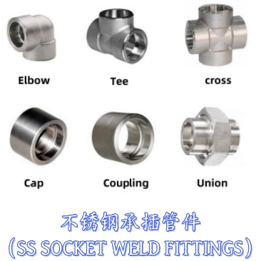
When piping requires direction changes, branching, or size reduction—especially in high-pressure, space-constrained environments—ASME B16.11 forged fittings are typically used. This standard applies to socket-weld and threaded forged fittings in nominal pipe sizes NPS 1/8 to NPS 4.
ASME B16.11 covers various fitting types, including 45° elbows, 90° elbows, equal/reducing tees, crosses, caps, couplings, plugs, bushings, and more.
Pressure ratings:
Socket Weld Fittings: Class 3000, 6000, 9000
Threaded Fittings: Class 2000, 3000, 6000
Socket Weld Fitting Specifications
Size Range: 1/8" to 4" (DN6 to DN100)
Pressure Ratings: Class 3000, 6000, 9000
Joint Type | Class | Grade of Connecting Pipes | Joint Type | Class | Grade of Connecting Pipes | |
SW | 3000 | Sch80 XS | THRD | 2000 | Sch80 XS | |
6000 | Sch160 | 3000 | Sch160 | |||
9000 | XXS | 6000 | XXS |
Socket weld fitting size range: 1/8 inch to 4 inches; Pressure rating: Class 3000 / 6000 / 9000
Size | 1/8″ to 4″ ( DN6 to DN100) |
Pressure | Class 3000, 6000, 9000 LBS |
Standard | ASME B16.11, BS3799, MSS SP-79 / 83 / 85 / 97 |
Types | Socket Weld Elbow,Tee,Cross,Cap,Coupling,Boss,Reducer Insert and Union. |
Carbon Steel | ASTM A105 / A105N, ASTM A350 LF2/LF3, A694 F42 / 46 / 56 / 60 / 65 |
Alloy Steel | ASTM A182 F11 / F12 / F5 / F9 / F91 / F92 / F22 |
Stainless Steel | ASTM A182 F304/304L/304H, F316/316L, F310S, F317, F347, F904L |
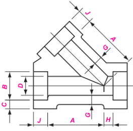
Dimension of Socket Weld Elbow \ Tee \ Cross


| SW 45° Elbow | SW 90° Elbow | SW Tee | SW Cross | ||||||||||||||||||
| GB/T 14383 ASME B16.11 | |||||||||||||||||||||
| Nominal Size | Socket Bore Dia. | Bore Dia. of Fittings | Socket Wall Thickness | Body Wall | Depth of Socket | Center to Bottom of Socket | |||||||||||||||
| DN | NPS | B | D | C | G min | J min | A | ||||||||||||||
| 3000 | 6000 | 9000 | 3000 | 6000 | 9000 | 3000 | 6000 | 9000 | 90 Elbow,Tee,Cross | 45 Elbow | |||||||||||
| ave | min | ave | min | ave | min | 3000 | 6000 | 9000 | 3000 | 6000 | 9000 | ||||||||||
| 6 | 1/8 | 10.9 | 6.1 | 3.2 | 3.18 | 3.18 | 3.96 | 3.43 | 2.41 | 3.15 | 9.5 | 11 | 11 | 8 | 8 | ||||||
| 8 | 1/4 | 14.3 | 8.5 | 5.6 | 3.78 | 3.3 | 4.6 | 4.01 | 3.02 | 3.68 | 9.5 | 11 | 13.5 | 8 | 8 | ||||||
| 10 | 3/8 | 17.7 | 11.8 | 8.4 | 4.01 | 3.5 | 5.03 | 4.37 | 3.2 | 4.01 | 9.5 | 13.5 | 15.5 | 8 | 11 | ||||||
| 15 | 1/2 | 21.9 | 15 | 11 | 5.6 | 4.67 | 4.09 | 5.97 | 5.18 | 9.53 | 8.18 | 3.73 | 4.78 | 7.47 | 9.5 | 15.5 | 19 | 25.5 | 11 | 12.5 | 15.5 |
| 20 | 3/4 | 27.3 | 20.2 | 14.8 | 10.3 | 4.9 | 4.27 | 6.96 | 6.04 | 9.78 | 8.56 | 3.91 | 5.56 | 7.82 | 12.5 | 19 | 22.5 | 28.5 | 13 | 14 | 19 |
| 25 | 1 | 34 | 25.9 | 19.9 | 14.4 | 5.69 | 4.98 | 7.92 | 6.93 | 11.38 | 9.96 | 4.55 | 6.35 | 9.09 | 12.5 | 22.5 | 27 | 32 | 14 | 17.5 | 20.5 |
| 32 | 11/4 | 42.8 | 34.3 | 28.7 | 22 | 6.07 | 5.28 | 7.92 | 6.93 | 12.14 | 10.62 | 4.85 | 6.35 | 9.7 | 12.5 | 27 | 32 | 35 | 17.5 | 20.5 | 22.5 |
| 40 | 11/2 | 48.9 | 40.1 | 33.2 | 27.2 | 6.35 | 5.54 | 8.92 | 7.8 | 12.7 | 11.12 | 5.08 | 7.14 | 10.15 | 12.5 | 32 | 38 | 38 | 20.5 | 25.5 | 25.5 |
| 50 | 2 | 61.2 | 51.7 | 42.1 | 37.4 | 6.93 | 6.04 | 10.92 | 9.5 | 13.84 | 12.12 | 5.54 | 8.74 | 11.07 | 16 | 38 | 41 | 54 | 25.5 | 28.5 | 28.5 |
| 65 | 21/2 | 73.9 | 61.2 | 8.76 | 7.62 | 7.01 | 16 | 41 | 28.5 | ||||||||||||
| 80 | 3 | 89.9 | 76.4 | 9.52 | 8.3 | 7.62 | 16 | 57 | 32 | ||||||||||||
| 100 | 4 | 115.5 | 100.7 | 10.69 | 9.35 | 8.56 | 19 | 66.5 | 41 | ||||||||||||
Dimension of Socket Weld Coupling \ Boss \ Cap \ 45 Deg Latera


| SW Coupling | SW Half-Coupling | Boss | SW Cap | SW 45° Latera | ||||||||||||||||||||
| GB/T 14383 ASME B16.11 | ||||||||||||||||||||||||
| Nominal Size | Socket Bore Dia. | Bore Dia. of Fittings | Socket Wall Thickness | Body Wall | Depth of Socket | Laying Lengths | Laying Lengths | End Wall Thickness | Center to Bottom of Socket | |||||||||||||||
| DN | NPS | B | D | C | G min | J min | E | F | K min | A | H | |||||||||||||
| 3000 | 6000 | 9000 | 3000 | 6000 | 9000 | 3000 | 6000 | 9000 | 3000 | 6000 | 9000 | 3000 | 6000 | 3000 | 6000 | |||||||||
| ave | min | ave | min | ave | min | |||||||||||||||||||
| 6 | 1/8 | 10.9 | 6.1 | 3.2 | 3.18 | 3.18 | 3.96 | 3.43 | 2.41 | 3.15 | 9.5 | 6.5 | 16 | 4.8 | 6.4 | |||||||||
| 8 | 1/4 | 14.3 | 8.5 | 5.6 | 3.78 | 3.30 | 4.6 | 4.01 | 3.02 | 3.68 | 9.5 | 6.5 | 16 | 4.8 | 6.4 | |||||||||
| 10 | 3/8 | 17.7 | 11.8 | 8.4 | 4.01 | 3.50 | 5.03 | 4.37 | 3.2 | 4.01 | 9.5 | 6.5 | 17.5 | 4.8 | 6.4 | |||||||||
| 15 | 1/2 | 21.9 | 15 | 11 | 5.6 | 4.67 | 4.09 | 5.97 | 5.18 | 9.53 | 8.18 | 3.73 | 4.78 | 7.47 | 9.5 | 9.5 | 22.5 | 6.4 | 7.9 | 11.2 | 41 | 51 | 9.5 | 11 |
| 20 | 3/4 | 27.3 | 20.2 | 14.8 | 10.3 | 4.9 | 4.27 | 6.96 | 6.04 | 9.78 | 8.56 | 3.91 | 5.56 | 7.82 | 12.5 | 9.5 | 24 | 6.4 | 7.9 | 12.7 | 51 | 60 | 11 | 13 |
| 25 | 1 | 34 | 25.9 | 19.9 | 14.4 | 5.69 | 4.98 | 7.92 | 6.93 | 11.38 | 9.96 | 4.55 | 6.35 | 9.09 | 12.5 | 12.5 | 28.5 | 9.6 | 11.2 | 14.2 | 60 | 71 | 13 | 16 |
| 32 | 11/4 | 42.8 | 34.3 | 28.7 | 22 | 6.07 | 5.28 | 7.92 | 6.93 | 12.14 | 10.62 | 4.85 | 6.35 | 9.7 | 12.5 | 12.5 | 30 | 9.6 | 11.2 | 14.2 | 71 | 81 | 16 | 17 |
| 40 | 11/2 | 48.9 | 40.1 | 33.2 | 27.2 | 6.35 | 5.54 | 8.92 | 7.8 | 12.7 | 11.12 | 5.08 | 7.14 | 10.15 | 12.5 | 12.5 | 32 | 11.2 | 12.7 | 15.7 | 81 | 98 | 17 | 21 |
| 50 | 2 | 61.2 | 51.7 | 42.1 | 37.4 | 6.93 | 6.04 | 10.92 | 9.5 | 13.84 | 12.12 | 5.54 | 8.74 | 11.07 | 16 | 19.0 | 30 | 9.6 | 11.2 | 14.2 | 71 | 81 | 16 | 17 |
| 65 | 21/2 | 73.9 | 61.2 | 8.76 | 7.62 | 7.01 | 16 | 19.0 | 43 | 15.7 | 19 | 151 | 30 | |||||||||||
| 80 | 3 | 89.9 | 76.4 | 9.52 | 8.30 | 7.62 | 16 | 19.0 | 44.5 | 19.0 | 22.4 | 184 | 57 | |||||||||||
| 100 | 4 | 115.5 | 100.7 | 10.69 | 9.35 | 8.56 | 19 | 19.0 | 48 | 22.4 | 28.4 | 201 | 66 | |||||||||||
Tolerance of Socket Weld Fittings
| Nominal Size | All Fittings | Elbows, Tees & Crosses | Couplings | Half- Couplings | Reducer Inserts | Unions | |||||||||||||
| Socket Bore Dia. | Bore Dia. of Fittings | Center to Bottom of Socket | Laying Lengths | Laying Lengths | Laying Length | Shank Dia. | Length | Laying Length | |||||||||||
| DN | NPS | B | D | A H | E | F | A | SD | SL | E | |||||||||
| 6~8 | 1/8~1/4 | +0.4 0 | +1.5 0 | ± 1.0 | ± 1.5 | ± 1.0 | +1.5 0 | ± 0.25 | 0 -1.5 | ± 1.5 | |||||||||
| 10~20 | 3/8~3/4 | +0.4 0 | +1.5 0 | ± 1.5 | ± 3.0 | ± 1.5 | +1.5 0 | ± 0.25 | 0 -1.5 | ± 3.0 | |||||||||
| 25~40 | 1~11/2 | +0.4 0 | +1.5 0 | ± 2.0 | ± 4.0 | ± 2.0 | +2.0 0 | ± 0.25 | 0 -2.0 | ± 4.0 | |||||||||
| 50 | 2 | +0.5 0 | +1.5 0 | ± 2.0 | ± 4.0 | ± 2.0 | +2.0 0 | ± 0.5 | 0 -2.0 | ± 4.0 | |||||||||
| 65~80 | 21/2~3 | +0.5 0 | +3.0 0 | ± 2.5 | ± 5.0 | ± 2.5 | +2.5 0 | ± 0.5 | 0 -2.5 | ± 5.0 | |||||||||
| 100 | 4 | +0.5 0 | +3.0 0 | ± 2.5 | ± 5.0 | ± 2.5 | +2.5 0 | ± 0.7 | 0 -2.5 | - | |||||||||

Threaded Fitting Types: Threaded 45° Elbow, 90° Elbow, Tee, Cross, Street Elbow, Coupling, Half Coupling, Cap, Plug, Bushing.
Size Range: 1/8" to 4" (DN6 to DN100)
Pressure Ratings: Class 2000, 3000, 6000
Size | 1/8″ to 4″ ( DN6 to DN100) |
Pressure | Class 2000, 3000, 6000 LBS |
Standard | ASME B16.11, BS3799, MSS SP-79 / 83 / 85 / 95/97 |
Types | Threaded Elbow,Tee,Cross,Cap,Coupling,Boss,Cap |
Carbon Steel | ASTM A105 / A105N, ASTM A350 LF2/LF3, A694 F42 / 46 / 56 / 60 / 65 |
Alloy Steel | ASTM A182 F11 / F12 / F5 / F9 / F91 / F92 / F22 |
Stainless Steel | ASTM A182 F304/304L/304H, F316/316L, F310S, F317, F347, F904L |
Dimension of Threaded Fittings


Threaded 45 Elbow | Threaded 45 ° Elbow | Threaded Tee | Threaded Cross | ||||||||||||
GB/T 14383 ASME B16.11 | |||||||||||||||
Nominal Size | Center-to-End | Outside Diameter of Band | Wall Thickness | Length of Thread | |||||||||||
DN | NPS | A | H | G min | L5 min | L2 min | |||||||||
90° Elbows, Tees, Crosses | 45 ° Elbows | ||||||||||||||
2000 | 3000 | 6000 | 2000 | 3000 | 6000 | 2000 | 3000 | 6000 | 2000 | 3000 | 6000 | ||||
6 | 1/8 | 21 | 21 | 25 | 17 | 17 | 19 | 22 | 22 | 25 | 3.18 | 3.18 | 6.35 | 6.4 | 6.7 |
8 | 1/4 | 21 | 25 | 28 | 17 | 19 | 22 | 22 | 25 | 33 | 3.18 | 3.30 | 6.60 | 8.1 | 10.2 |
10 | 3/8 | 25 | 28 | 33 | 19 | 22 | 25 | 25 | 33 | 38 | 3.18 | 3.51 | 6.98 | 9.1 | 10.4 |
15 | 1/2 | 28 | 33 | 38 | 22 | 25 | 28 | 33 | 38 | 46 | 3.18 | 4.09 | 8.15 | 10.9 | 13.6 |
20 | 3/4 | 33 | 38 | 44 | 25 | 28 | 33 | 38 | 46 | 56 | 3.18 | 4.32 | 8.53 | 12.7 | 13.9 |
25 | 1 | 38 | 44 | 51 | 28 | 33 | 35 | 46 | 56 | 62 | 3.68 | 4.98 | 9.93 | 14.7 | 17.3 |
32 | 1 1/4 | 44 | 51 | 60 | 33 | 35 | 43 | 56 | 62 | 75 | 3.89 | 5.28 | 10.59 | 17.0 | 18.0 |
40 | 1 1/2 | 51 | 60 | 64 | 35 | 43 | 44 | 62 | 75 | 84 | 4.01 | 5.56 | 11.07 | 17.8 | 18.4 |
50 | 2 | 60 | 64 | 53 | 43 | 44 | 52 | 75 | 84 | 102 | 4.27 | 7.14 | 12.09 | 19.0 | 19.2 |
65 | 2 1/2 | 76 | 83 | 95 | 52 | 52 | 64 | 92 | 102 | 121 | 5.61 | 7.65 | 15.29 | 23.6 | 28.9 |
80 | 3 | 86 | 95 | 106 | 64 | 64 | 79 | 109 | 121 | 146 | 5.99 | 8.84 | 16.64 | 25.9 | 30.5 |
100 | 4 | 106 | 114 | 114 | 79 | 79 | 79 | 146 | 152 | 152 | 6.55 | 11.18 | 18.67 | 27.7 | 33 |


Coupling | Half-Coupling | Boss | Cap | |||||||
Nominal Size | End-to-End | End-to-End | Outside Diameter | End Wall | Length of Thread | |||||
DN | NPS | W | P | D | G min | L5 min | L2 min | |||
3000 & 6000 | 3000 | 6000 | 3000 | 6000 | 3000 | 6000 | ||||
6 | 1/8 | 32 | 19 | 16 | 22 | 4.8 | 6.4 | 6.7 | ||
8 | 1/4 | 35 | 25 | 27 | 19 | 25 | 4.8 | 6.4 | 8.1 | 10.2 |
10 | 3/8 | 38 | 25 | 27 | 22 | 32 | 4.8 | 6.4 | 9.1 | 10.4 |
15 | 1/2 | 48 | 32 | 33 | 28 | 38 | 6.4 | 7.9 | 10.9 | 13.6 |
20 | 3/4 | 51 | 37 | 38 | 35 | 44 | 6.4 | 7.9 | 12.7 | 13.9 |
25 | 1 | 60 | 41 | 43 | 44 | 57 | 9.7 | 11.2 | 14.7 | 17.3 |
32 | 1 1/4 | 67 | 44 | 46 | 57 | 64 | 9.7 | 11.2 | 17.0 | 18.0 |
40 | 1 1/2 | 79 | 44 | 48 | 64 | 76 | 11.2 | 12.7 | 17.8 | 18.4 |
50 | 2 | 86 | 48 | 51 | 76 | 92 | 12.7 | 15.7 | 19.0 | 19.2 |
65 | 2 1/2 | 92 | 60 | 64 | 92 | 108 | 15.7 | 19.0 | 23.6 | 28.9 |
80 | 3 | 108 | 65 | 68 | 108 | 127 | 19.0 | 22.4 | 25.9 | 30.5 |
100 | 4 | 121 | 68 | 75 | 140 | 159 | 22.4 | 28.4 | 27.7 | 33.0 |
Tolerances
Nominal Size | Elbows,Tees & Crosses | Couplings | Half- couplings | |
Center-to-End | End-to-End | End-to-End | ||
DN | NPS | A J | W | W/ 2 |
6~8 | 1/8~1/4 | ± 1.0 | ± 1.0 | ± 1.0 |
10~20 | 3/8~3/4 | ± 1.5 | ± 1.5 | ± 1.5 |
25~50 | 1~2 | ± 2.0 | ± 2.0 | ± 2.0 |
65~100 | 21/2~4 | ± 2.5 | ± 2.5 | ± 2.5 |
ASME B16.11 forged fittings are available in various materials. As a professional fitting manufacturer, we produce forged fittings in:
Carbon Steel: ASTM A105/A105N
Features: Corrosion resistance, strong pressure capacity, easy installation
Low Temperature Steel: ASTM A350 LF2/LF3
Features: Excellent low-temperature performance, good mechanical properties, corrosion resistance, hydrogen embrittlement resistance
Line Pipe Steel: A694 F42/F46/F52/F56/F65/F70
Features: High tensile strength/toughness, relatively low material cost
Alloy Steel: ASTM A182 F5/F9/F11/F12/F22/F91/F92
Features: Excellent wear resistance for long life in abrasive environments
Stainless Steel: A182 F304/304L/304H - F904L
Features: Corrosion resistance, high strength, good high/low-temperature performance, non-magnetic, high surface finish, easy processing/installation, environmentally friendly/recyclable
High Pressure Resistance: Forged fittings undergo high-temperature forging and heat treatment, providing higher strength and durability to withstand high pressure, high temperature, and corrosive media.
Consistent Quality: Strict quality control and inspection during manufacturing ensure consistent product quality, reducing risks of leakage and failure.
Long Service Life: Strict material and process requirements ensure high reliability and long service life.
Versatile Connection Methods: Suitable for various connection types (threaded, welded, socket), offering broad applicability.
Environmentally Friendly: Materials and processes comply with standards, ensuring safety and no harm to the environment or human health.
Although both belong to the B16 family and are often used together, they have fundamental differences:
B16.5 defines flanges. Their function is to create removable connections between pipes and equipment (pumps, valves) or between pipe sections, typically using bolts and gaskets.
B16.11 defines fittings (connectors). Their function is to change direction, create branches, or change pipe size. Once welded or tightened, they form permanent (welded) or semi-permanent (threaded) connections.
Size: B16.5 covers a wide range (½" to 24"). B16.11 focuses on small diameters (≤ 4").
Pressure Rating: B16.5 uses Class (150 to 2500) for pressure-temperature ratings. B16.11 fittings are identified by ratings like 2000, 3000, 6000, 9000, indicating their strength based on specific material groups and temperatures, corresponding to compatible pipe schedules.
While B16.5 includes socket weld and threaded flanges, its primary method is flanged connection (bolted) .
B16.11 fittings have specific connection methods: Socket Weld (SW) or Threaded (NPT) , for direct connection to pipes.
Despite their differences, they are inseparable in practical engineering.
In a typical high-pressure system, a B16.5 socket weld flange often serves as the key node connecting B16.11 fittings. For example, when transitioning from a small-bore high-pressure line (using B16.11 socket weld fittings) to equipment, a B16.5 socket weld or threaded flange is used to connect to the equipment's bolted flange.
Their design logic is unified. B16.11 3000LB and 6000LB fittings are designed to match piping systems using B16.5 Class 600, Class 1500, or higher flanges. This ensures pressure integrity across the entire system.
Both primarily use forged materials (like ASTM A105 carbon steel, A182 F304/316 stainless steel) and adhere to the strict material requirements of the ASME Boiler and Pressure Vessel Code.
