

Views: 5 Author: Site Editor Publish Time: 2026-03-17 Origin: Site


ASME standard carbon steel flanges and fittings are the two most widely used pipeline components in modern industrial pipeline engineering. Shanghai Zucheng Pipe Fittings Manufacturing Co., Ltd. has been deeply involved in the field of industrial pipeline construction for many years, and has a profound understanding of various international standard accessories and flange products, winning the trust of domestic and foreign customers.
In January this year, we received an order from an overseas long-term customer for American standard carbon steel flange and fitting products. In this order, flanges were manufactured according to ASME B16.5, fittings included butt-welding elbows, tees, and forged branch outlets. Butt-welding fittings were produced according to ASME B16.9, while socket-welding branch outlets were forged according to MSS SP-97.
ASME standard carbon steel flanges and fittings are the products we are most familiar with. Therefore, although the customer's product description information was incomplete, based on years of experience in handling such products, we quickly provided appropriate quotations and successfully signed the contract.
| ITEM | DESCRIPTION | QTY | UNIT |
| 01 | Elbow; Carbon Steel. 90 Deg. Butt Weld. 2” Sch-40 Long Radius | 20 | PCS |
| 02 | Flange; Weld Neck. RF 6" x 300 lbs. Sch. 80. Carbon Steel. Grade ASME B16.5 A105. | 20 | PCS |
| 03 | Flange; Weld Neck. RF 2" x 300#. Carbon Steel A105 | 40 | PCS |
| 07 | Sock-O-Let; Carbon Steel. 3000 lbs. 2" | 20 | PCS |
| 08 | Flange; Weld Neck. RF 4’’ x 300 lbs. Carbon Steel. ASME B16.5 A105 | 112 | PCS |
| 09 | Elbow; Carbon Steel. 90 Deg. Butt Weld. 4” Sch-40 Long Radius | 38 | PCS |
| 10 | Sock-O-Let; Carbon Steel. 3000 lbs. 3/4" | 75 | PCS |
| 11 | Tee; Reducing. Carbon Steel. 6” x 4” Sch-40. ASTM A106 Grade B/WPB; ASME B16.9 | 38 | PCS |
| 12 | Elbow; Carbon Steel. 90 Deg. Butt Weld. 6" Sch-40 Short Radius | 40 | PCS |
| TOTAL | 403 | PCS | |


ASME B16.5 "Pipe Flanges and Flange Fittings," as one of the most widely used standards in the forged flange manufacturing field, specifies design, manufacturing, inspection, and connection requirements for pipe flanges and flange fittings, enabling forged flange products manufactured by different manufacturers according to this standard to be interchangeable while meeting structural strength and pressure-bearing requirements needed for different pipeline designs.
ASME B16.5 carbon steel welded neck flange, with its excellent structural strength, wide pressure coverage range, and strict international standard requirements, has become an indispensable core connecting component in modern industrial pipeline engineering.
The ASME B16.5 standard covers nominal size range from 1/2 inch to 24 inches (DN15-DN600). For flanges larger than 24 inches, ASME B16.47 standard should be referenced. ASME B16.5 carbon steel weld neck flanges have 7 pressure classes:
Class 150, Class 300, Class 400, Class 600, Class 900, Class 1500, Class 2500.
Welded neck flange refers to a flange form with a conical high neck, which is connected to the pipeline through neck butt welding. Its core structural features include:
Conical high neck design: The flange neck has a conical transition, effectively dispersing and transmitting stress from the flange ring to the pipe body, significantly reducing stress concentration at the base of the flange.
Butt-welding connection method: The flange neck end is machined with welding bevel (typically 37.5 degrees) for circumferential butt-welding with the pipe, forming a full penetration structure.
Forging process: Typically manufactured using integral forging process, with continuous internal metal flow lines, mechanical properties superior to cast or cut pieces.
This structural design makes weld neck flanges particularly suitable for pipeline systems with severe pressure fluctuations, high temperature/pressure, low temperature cryogenic, or conveying flammable/explosive media under harsh working conditions.
Common sealing face types include:
Sealing Face Type | Code | Characteristics Description |
Raised Face | RF | Most common type, default with raised face per ASME B16.5, surface has concentric or spiral serrations |
Flat Face | FF | Sealing face covers entire flange face, commonly used for low pressure or cast iron equipment connections |
Male-Female Face | MFM | Divided into male face and female face, used together, accurate positioning |
Tongue-Groove Face | TG | Divided into tongue face and groove face, excellent sealing performance, suitable for flammable/explosive media |
Ring Joint Face | RTJ | Used for high pressure conditions, paired with metal ring gasket |
Common materials for ASME B16.5 carbon steel weld neck flanges and their applicable temperatures:
Material Standard | Material Grade | Characteristics and Application |
ASTM A105 | A105 | Most common carbon steel flange material, suitable for normal to high temperature conditions |
ASTM A350 | LF2 Class 1 | Low temperature carbon steel, impact test temperature -46°C, suitable for low temperature conditions |
ASTM A350 | LF2 Class 2 | Low temperature carbon steel, impact test temperature -18°C |
ASTM A694 | F42-F70 | Line pipe steel flange, suitable for high pressure gas transmission pipelines |
GB Standard | 20#, 16Mn, Q235 | Common substitute materials, suitable for non-standard or domestic projects |

| Nominal Pipe Size | A | B | C | D | E | F | G | H | I | J | Weight | |
| inch | mm | mm | mm | mm | mm | mm | mm | mm | Holes | mm | mm | kg / piece |
| 1/2 | 21.30 | 95.20 | 15.70 | 14.20 | 52.30 | 21.30 | 38.10 | 35.00 | 4 | 15.70 | 66.55 | 0.75 |
| 3/4 | 26.70 | 117.3 | 20.80 | 15.70 | 57.15 | 26.70 | 47.70 | 42.90 | 4 | 19.00 | 82.50 | 1.26 |
| 1 | 33.40 | 123.9 | 26.70 | 17.50 | 62.00 | 33.50 | 53.80 | 50.80 | 4 | 19.00 | 88.90 | 1.52 |
| 1 1/4 | 42.20 | 133.3 | 35.10 | 19.00 | 65.00 | 42.20 | 63.50 | 63.50 | 4 | 19.00 | 98.50 | 2.03 |
| 1 1/2 | 48.30 | 155.4 | 40.90 | 20.60 | 68.30 | 48.30 | 69.85 | 73. 15 | 4 | 22.30 | 114.3 | 2.89 |
| 2 | 60.30 | 165. 1 | 52.60 | 22.30 | 69.85 | 60.45 | 84.00 | 91.90 | 8 | 19.00 | 127.0 | 3.4 |
| 2 1/2 | 73.00 | 190.5 | 62.70 | 25.40 | 76.20 | 73.15 | 100.0 | 104.6 | 8 | 22.30 | 149.3 | 5.17 |
| 3 | 88.90 | 209.5 | 78.00 | 28.40 | 79.25 | 88.90 | 117.3 | 127.0 | 8 | 22.30 | 168.1 | 6.93 |
| 3 1/2 | 101.6 | 228.6 | 90.20 | 30.20 | 81.00 | 101.6 | 133.3 | 139.7 | 8 | 22.30 | 184.1 | 8.67 |
| 4 | 114.3 | 254.0 | 102.4 | 31.70 | 85.80 | 114.3 | 146.0 | 157.2 | 8 | 22.30 | 200.1 | 11.2 |
| 5 | 141.3 | 279.4 | 128.3 | 35.00 | 98.50 | 141.2 | 177.8 | 185.7 | 8 | 22.30 | 234.9 | 15.1 |
| 6 | 168.3 | 317.5 | 154.2 | 36.50 | 98.50 | 168.4 | 206.2 | 215.9 | 12 | 22.30 | 269.7 | 19.1 |
| 8 | 219.1 | 381.0 | 202.7 | 41.10 | 111.2 | 219.2 | 260.3 | 269.7 | 12 | 25.40 | 330.2 | 29.9 |
| 10 | 273.0 | 444.5 | 254.5 | 47.70 | 117.3 | 273.0 | 320.5 | 323.8 | 16 | 28.40 | 387.3 | 42.7 |
| 12 | 323.8 | 520.7 | 304.8 | 50.80 | 130.0 | 323.8 | 374.6 | 381.0 | 16 | 31.70 | 450.8 | 61.8 |
| 14 | 355.6 | 584.2 | To be specified by the Purchaser | 53.80 | 142.7 | 355.6 | 425.4 | 412.7 | 20 | 31.70 | 514.3 | 85.8 |
| 16 | 406.4 | 647.7 | 57.15 | 146.0 | 406.4 | 482.6 | 469.9 | 20 | 35.00 | 571.5 | 106 | |
| 18 | 457.2 | 711.2 | 60.45 | 158.7 | 457.2 | 533.4 | 533.4 | 24 | 35.00 | 628.6 | 131 | |
| 20 | 508.0 | 774.7 | 63.50 | 162.0 | 508.0 | 587.2 | 584.2 | 24 | 35.00 | 685.8 | 158 | |
| 24 | 609.6 | 914.4 | 69.85 | 168.1 | 609.6 | 701.5 | 692.1 | 24 | 41.10 | 812.8 | 230 | |
ASTM A234 WPB butt-welding fittings are fittings manufactured using carbon steel as raw material, featuring good welding performance, mechanical properties, and corrosion resistance. The carbon content in their chemical composition is ≤0.30%, with other alloying elements added to enhance performance. These fittings possess high strength and hardness while maintaining good plasticity, suitable for manufacturing various pressure pipelines and pressure vessels.
ASTM A234 is a material standard established by ASTM International, specifying clear requirements for chemical composition, mechanical properties, heat treatment, impact testing, etc., of carbon and alloy steel butt-welding fittings. The standard requires materials to meet specific chemical composition requirements to ensure fitting strength and corrosion resistance.
ASTM A234 WPB is the most commonly used carbon steel material for butt-welding fittings, featuring excellent low temperature toughness, corrosion resistance, and high temperature strength. It is mainly used for manufacturing high pressure valves, fittings, chemical equipment, etc.
WPB is the abbreviation of the following English words:
W = WELDABLE / wrought
P = RELATED TO P NUMBER OF ALLOY MATERIAL
B = REFER TO MINIMUM YIELD OF MATERIAL

ASME B16.9 is the standard for factory-made wrought steel butt-welding fittings, issued by the American Society of Mechanical Engineers. This standard covers dimensions, tolerances, design, and marking requirements for butt-welding fittings of carbon steel, alloy steel, and stainless steel. ASME B16.9 butt-welding elbows, as the most important and widely used fitting type among them, are used in pipeline systems to change medium flow direction.
The ASME B16.9 standard applies to butt-welding fittings with nominal size from NPS 1/2 to NPS 48 (DN15-DN1200), including butt-welding elbows, tees, reducers, caps, etc.
The pressure rating of ASME B16.9 butt-welding fittings depends on the wall thickness schedule of the connected pipe. The standard specifies that the pressure-bearing capacity of fittings should not be lower than that of straight pipe of the same material with the same wall thickness schedule.
By Bending Radius:
Type | Code | Bending Radius | Characteristics and Application |
Long Radius Elbow | LR | 1.5D (1.5 times nominal diameter) | Most common type, low fluid resistance, suitable for most working conditions |
Short Radius Elbow | SR | 1.0D (1.0 times nominal diameter) | Used in space-constrained situations, higher fluid resistance |
Bend | 3D/5D etc. | 3 or 5 times nominal diameter | Special requirements, such as solid material conveying, low resistance requirements |
By Bending Angle:
Angle | Description |
45° Elbow | Common angle, used for 45° direction change |
90° Elbow | Most common angle, used for 90° right-angle turn |
180° Elbow | Also called return elbow, used for reverse 180° turn |
By Manufacturing Process:
Type | Manufacturing Method | Applicable Size | Characteristics |
Seamless Elbow | Pipe billet hot pushing or cold forming | NPS 2" and below, or large diameter special requirements | No longitudinal weld, good overall performance |
Welded Elbow | Steel plate rolling and welding | Typically NPS 2" and above | Lower cost, weld requires inspection |

BW 90 LR/SR Elbow | BW 45 LR Elbow | ||||
GB/T 12459 GB/T 13401 ASME B16.9 | |||||
Nominal Size | Outside Diameter at Bevel | Center to End | |||
90° Elbows | 45° Elbows | ||||
DN | NPS | OD | A | B | |
LR | SR | LR | |||
15 | 1/2 | 21.3 | 38 | 16 | |
20 | 3/4 | 26.7 | 38 | 19 | |
25 | 1 | 33.4 | 38 | 25 | 22 |
32 | 1 1/4 | 42.2 | 48 | 32 | 25 |
40 | 1 1/2 | 48.3 | 57 | 38 | 29 |
50 | 2 | 60.3 | 76 | 51 | 35 |
65 | 2 1/2 | 73.0 | 95 | 64 | 44 |
80 | 3 | 88.9 | 114 | 76 | 51 |
90 | 3 1/2 | 101.6 | 133 | 4、89 | 57 |
100 | 4 | 114.3 | 152 | 102 | 64 |
125 | 5 | 141.3 | 190 | 127 | 79 |
150 | 6 | 168.3 | 229 | 152 | 95 |
200 | 8 | 219.1 | 305 | 203 | 127 |
250 | 10 | 273.0 | 381 | 254 | 159 |
300 | 12 | 323.8 | 457 | 305 | 190 |
350 | 14 | 355.6 | 533 | 356 | 222 |
400 | 16 | 406.4 | 610 | 406 | 254 |
450 | 18 | 457.0 | 686 | 457 | 286 |
500 | 20 | 508.0 | 762 | 508 | 318 |
550 | 22 | 559.0 | 838 | 559 | 343 |
600 | 24 | 610.0 | 914 | 610 | 381 |
650 | 26 | 660.0 | 991 | 660 | 406 |
700 | 28 | 711.0 | 1067 | 711 | 438 |
750 | 30 | 762.0 | 1143 | 762 | 470 |
800 | 32 | 813.0 | 1219 | 813 | 502 |
850 | 34 | 864.0 | 1295 | 864 | 533 |
900 | 36 | 914.0 | 1372 | 914 | 565 |
950 | 38 | 965.0 | 1448 | 965 | 600 |
1000 | 40 | 1016.0 | 1524 | 1016 | 632 |
1050 | 42 | 1067.0 | 1600 | 1067 | 660 |
1100 | 44 | 1118.0 | 1676 | 1118 | 695 |
1150 | 46 | 1168.0 | 1753 | 1168 | 727 |
1200 | 48 | 1219.0 | 1829 | 1219 | 759 |

ASTM A234 WPB butt-welding tee is a core fitting for achieving pipeline branching connections in industrial pipeline systems. It combines ASTM A234 WPB material standard and ASME B16.9 dimensional standard, widely used in pressure pipeline systems in petroleum, chemical, power, natural gas industries.
ASTM A234 WPB: Material standard, WPB stands for Weldable, P-number (material category), B grade strength requirement, is the most common material grade for carbon steel butt-welding fittings.
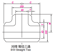
Butt-welding tee: Refers to a T-shaped fitting with welding bevels at two or three ends, connected to pipelines through butt-welding, used to divert or merge media in the main pipeline.
Execution standards: Dimensions and tolerances follow ASME B16.9, material follows ASTM A234.
Classification by Connection Type:
Type | Schematic | Characteristics and Application |
Equal Tee | Three outlets with same nominal size | Used for branches where main pipe and branch pipe have same diameter |
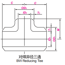
Reducing Tee | Main pipe size unchanged, branch pipe size smaller | Used for branches where main pipe size unchanged, branch pipe reduced |
By Structure Type:
Type | Manufacturing Method | Applicable Size | Characteristics |
Seamless Tee | Pipe billet hot extrusion forming | Small to medium diameter, typically NPS 12" and below | No weld, good overall performance |
Welded Tee | Steel plate rolling and welding | Large diameter, typically NPS 14" and above | Lower cost, weld requires inspection |
By Connection Angle:
Type | Angle | Description |
Straight Tee | 90° | Branch perpendicular to main pipe, most common type |
Lateral Tee | 45° or other angles | Special design, used for specific flow direction requirements |
| Nominal Size | Outside Diameter at Bevel | Center to End | ||
| DN | NPS | OD | C | M |
| 15 | 1/2 | 21.3 | 25 | 25 |
| 20 | 3/4 | 26.7 | 29 | 29 |
| 25 | 1 | 33.4 | 38 | 38 |
| 32 | 1.1/4 | 42.2 | 48 | 48 |
| 40 | 1.1/2 | 48.3 | 57 | 57 |
| 50 | 2 | 60.3 | 64 | 64 |
| 65 | 2.1/2 | 73.0 | 76 | 76 |
| 80 | 3 | 88.9 | 86 | 86 |
| 90 | 3.1/2 | 101.6 | 95 | 95 |
| 100 | 4 | 114.3 | 105 | 105 |
| 125 | 5 | 141.3 | 124 | 124 |
| 150 | 6 | 168.3 | 143 | 143 |
| 200 | 8 | 219.1 | 178 | 178 |
| 250 | 10 | 273.0 | 216 | 216 |
| 300 | 12 | 323.8 | 254 | 254 |
| 350 | 14 | 355.6 | 279 | 279 |
| 400 | 16 | 406.4 | 305 | 305 |
| 450 | 18 | 457.0 | 343 | 343 |
| 500 | 20 | 508.0 | 381 | 381 |
| 550 | 22 | 559.0 | 419 | 419 |
| 600 | 24 | 610.0 | 432 | 432 |
| 650 | 26 | 660.0 | 495 | 495 |
| 700 | 28 | 711.0 | 521 | 521 |
| 750 | 30 | 762.0 | 559 | 559 |
| 800 | 32 | 813.0 | 597 | 597 |
| 850 | 34 | 864.0 | 635 | 635 |
| 900 | 36 | 914.0 | 673 | 673 |
| 950 | 38 | 965.0 | 711 | 711 |
| 1000 | 40 | 1016.0 | 749 | 749 |
| 1050 | 42 | 1067.0 | 762 | 762 |
| 1100 | 44 | 1118.0 | 813 | 813 |
| 1150 | 46 | 1168.0 | 851 | 851 |
| 1200 | 48 | 1219.0 | 889 | 889 |
Weight Chart
Nominal Size | Sch20 | Sch30 | STD | Sch40 | Sch60 | XS | Sch80 | Sch100 | Sch120 | Sch140 | Sch160 | XXS | |
DN | NPS | ||||||||||||
15 | 1/2 | 0.15 | 0.16 | 0.16 | 0.20 | 0.20 | 0.25 | 0.35 | |||||
32 | 11/4 | 0.46 | 0.55 | 0.55 | 0.70 | 0.70 | 0.91 | 1.26 | |||||
65 | 21/2 | 2.06 | 2.21 | 2.21 | 2.92 | 2.92 | - - | 3.81 - | 5.21 | ||||
125 | 5 | - | - | 9.08 | 9.08 | - - | 12.9 | 12.9 | - | 16.8 | - | 20.5 | 24.0 |
250 | 10 | 28.0 | 37.1 | 44.8 | 44.8 | 59.2 | 59.2 | 69.7 | 83.3 | 96.6 | 113 | 125 | 113 |
400 | 16 | 78.2 | 95.7 | 95.7 | 126 | 164 | 126 | 191 | 252 | 294 | 342 | 375 | |
550 | 22 | 185 | 241 305 - | 182 | - | 414 | 241 | 482 | 636 | 743 - | 846 | 947 | |
700 | 28 | 390 | 478 | 289 | - | 383 | |||||||
850 | 34 | 540 | 709 796 - | 429 | 714 872 - | 569 | |||||||
1000 | 40 | 598 | 791 | ||||||||||
1150 | 46 | 779 | 995 | ||||||||||
Nominal Size | All Fittings | 45°&90° Elbows & Tees, Crosses | 3D Radius Elbows | Returns | Caps | Reducers & Lap Joint Stub Ends | Lap Joint Stub Ends | ||||||
| DN | NPS | OD 3) 4) | ID 3) | A B C M | A B | O | K | U | E, E1 | H F | G | R | t |
| 15-65 | 1/2 -21/2 | +1.6 -0.8 | ± 0.8 | ± 2 | ± 3 | ± 6 | ± 6 | ± 1 | ± 3 | ± 2 | 0 -1 | 0 -1 | +1.6 0 |
| 80-90 | 3-31/2 | ± 1.6 | ± 1.6 | ± 2 | ± 3 | ± 6 | ± 6 | ± 1 | ± 3 | ± 2 | 0 -1 | 0 -1 | +1.6 0 |
| 100 | 4 | ± 1.6 | ± 1.6 | ± 2 | ± 3 | ± 6 | ± 6 | ± 1 | ± 3 | ± 2 | 0 -1 | 0 -2 | +1.6 0 |
| 125-200 | 5-8 | +2.4 -1.6 | ± 1.6 | ± 2 | ± 3 | ± 6 | ± 6 | ± 1 | ± 6 | ± 2 | 0 -1 | 0 -2 | +1.6 0 |
| 250-450 | 10-18 | +4.0 -3.2 | ± 3.2 | ± 2 | ± 3 | ± 10 | ± 6 | ± 2 | ± 6 | ± 2 | 0 -2 | 0 -2 | +3.2 0 |
| 500-600 | 20-24 | +6.4 -4.8 | ± 4.8 | ± 2 | ± 3 | ± 10 | ± 6 | ± 2 | ± 6 | ± 2 | 0 -2 | 0 -2 | +3.2 0 |
| 650-750 | 26-30 | +6.4 -4.8 | ± 4.8 | ± 3 | ± 6 | --- | --- | --- | ± 10 | ± 5 | --- | --- | --- |
| 800-1200 | 32-48 | +6.4 -4.8 | ± 4.8 | ± 5 | ± 6 | --- | --- | --- | ± 10 | ± 5 | --- | --- | --- |
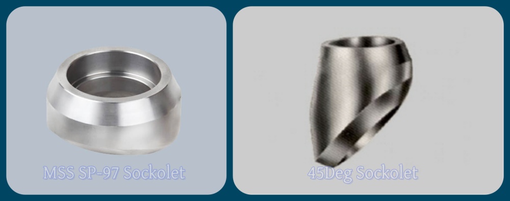
The outlet of the socket welding outlet is forged from high-quality round steel or steel billets, and consists of a saddle shaped base and a branch pipe connection port. The saddle shaped curved base design is easy to fit and weld with the outer wall of the main pipe, ensuring welding sealing; The top port is designed as a standard socket welding hole, with a smooth inner wall and a socket depth that meets standard specifications. It allows direct insertion into branch pipes and fixation through socket welding. The overall structure has strong pressure bearing capacity and smooth inner walls, effectively reducing medium resistance and eddy current losses.
Forged outlets effectively provide structural reinforcement, simplify construction, and adapt to high-pressure environments in industrial pipeline systems. The integral forging process enables them to withstand Class 3000, 6000, 9000 high pressure, widely used in various demanding industrial pipeline systems.
MSS SP-97 is the forged outlet fitting manufacturing standard established by the Manufacturers Standardization Society of the United States (MSS), full title "Integrally Reinforced Forged Branch Outlet Fittings", covering design, production, and inspection requirements for socket-welding, threaded, and butt-welding connection types of branch outlets. The main function of this standard is to unify technical parameters, ensuring interchangeability and reliability of products from different manufacturers.
Design requirements: Clearly specifies that branch outlets must be formed through forging, achieving "full reinforcement" through structural optimization; socket-welding ports must comply with socket depth and pressure requirements of ASME B16.11 standard.
Production specifications: Raw materials are limited to forgings, bars, or steel billets, requiring heat treatment processes such as normalizing, quenching to enhance performance.
Inspection standards: Mandatory magnetic particle testing (MT) and ultrasonic testing (UT).
Marking rules: Product surface must clearly display manufacturer information, material grade, pressure class, nominal size, and "SP-97" markings.
MSS SP-97 socket-welding branch outlets include 90-degree and 45-degree socket-welding branch outlets, with dimensional parameters and applicable scenarios varying:
90 Degree Socket-Welding Outlet
The 90-degree socket-welding branch outlet has branch socket port perpendicular to the main pipe, is the most common product type in pipeline systems, suitable for working environments with sufficient pipeline design space and requiring vertical branch connections. Its structural length is divided into Class 3000/6000/9000 three pressure grades, with higher-grade products having longer structural length at the same size to enhance stability.

| Outlet (DN) | B Min. (b) | C Max. | ||
| Class 3000 | Class 6000 | Class 9000 | ||
| 6 | 9.5 | 11 | 19 | - |
| 8 | 9.5 | 11 | 19 | - |
| 10 | 9.5 | 13 | 19 | - |
| 15 | 9.5 | 16 | 24 | 24 |
| 20 | 12.5 | 16 | 26 | 26 |
| 25 | 12.5 | 23 | 29 | 29 |
| 32 | 12.5 | 23 | 31 | 31 |
| 40 | 12.5 | 24 | 32 | 32 |
| 50 | 16.0 | 24 | 37 | 37 |
| 65 | 16.0 | 26 | - | - |
| 80 | 16.0 | 31 | - | - |
| 100 | 19.0 | 31 | - | - |
45 Degree Socket-Welding Outlet
The 45-degree socket-welding branch outlet has branch socket port designed at 45-degree angle to the main pipe, advantages include optimizing medium flow efficiency, reducing pressure loss, better matching pipeline structures with confined design spaces.
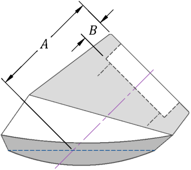
| Outlet (DN) | BMin.(b) | (Top of Fitting to Run Pipe) A | |||
| Class 3000 | Class 6000 | ||||
| A Min. | A Max. | A Min. | A Max. | ||
| 8 | 9.5 | 38.1 | 42.9 | 38.9 | 47.6 |
| 10 | 9.5 | 38.1 | 42.9 | 38.9 | 47.6 |
| 15 | 9.5 | 38.1 | 44.5 | 46.0 | 55.6 |
| 20 | 12.5 | 46.0 | 50.8 | 54.0 | 63.5 |
| 25 | 12.5 | 54.0 | 63.5 | 61.1 | 73.0 |
| 32 | 12.5 | 61.1 | 76.2 | 65.1 | 77.8 |
| 40 | 12.5 | 63.5 | 76.2 | 78.6 | 85.7 |
| 50 | 16.0 | 76.2 | 84.1 | 78.6 | 104.8 |
