

Views: 14 Author: Site Editor Publish Time: 2026-04-09 Origin: Site


In industrial piping systems, there is a seemingly simple yet critical pressure piping component—ASME B16.5 blind flange. It is not only an important part of the piping system but also key to ensuring maintenance safety and system sealing. Today, we will dive into the blind flange as defined by the ASME B16.5 standard, exploring its technical details and wide range of applications.
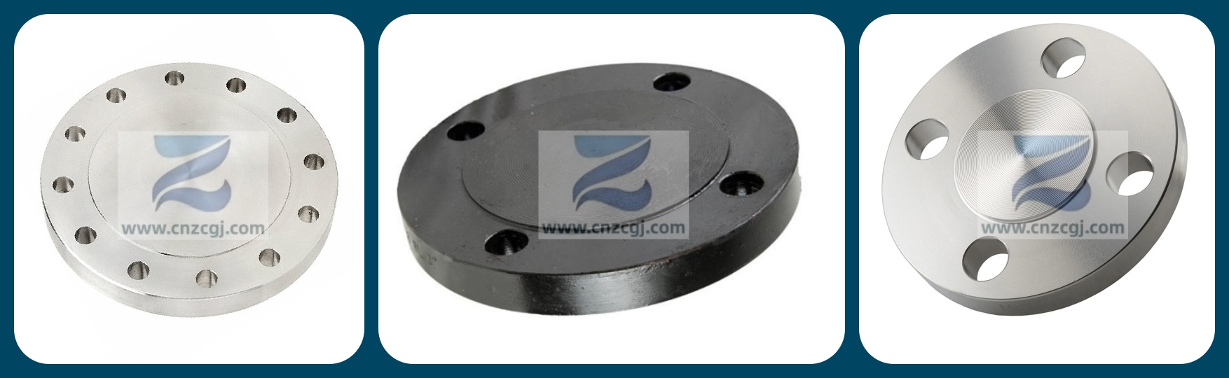
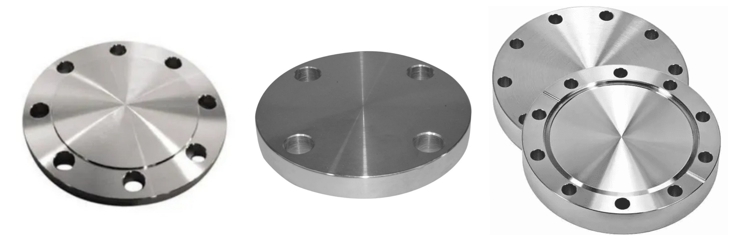
The ASME B16.5 blind flange is manufactured using a forging process, resulting in a solid, disc-like structure. Visually, the most significant difference between a blind flange and other flange types (such as Weld Neck or Slip-On flanges) is the absence of a hole in the center. Unlike weld neck flanges, the blind flange has a relatively simple structure, consisting mainly of a circular metal plate with bolt holes around its periphery for pipeline connections.
Its primary purpose is clear: to seal the end of a pipeline or an unused opening on a vessel. Whether it's a port reserved for future expansion or maintenance, or an unused connection on equipment, the blind flange provides a reliable, removable sealing solution.
Introduction to ASME B16.5 Flange Standard
ASME B16.5 is a core standard developed by the American Society of Mechanical Engineers (ASME) for pipe flanges and flange fittings. This standard covers nominal pipe sizes (NPS) from 1/2 inch to 24 inches and pressure classes from Class 150 to Class 2500. It specifies pressure-temperature ratings, materials, dimensions, tolerances, marking, and testing methods. It is one of the most widely used flange standards in the process industries, including oil & gas, chemical, and power generation.
Sealing Faces | Raised Face (RF), Flat Face (FF), Ring Type Joint (RTJ) |
Size Range | 1/2" – 24" / DN15 – DN600 |
Pressure | Class 150, 300, 400, 600, 900, 1500, 2500 lb |
Standards | ASME B16.5, ASME B16.47 Series A/B |
Carbon Steel | ASTM A105, 20# |
Low-Temp Steel | ASTM A350 LF2, 16Mn |
Pipeline Steel | ASTM A694 F42 / 46 / 56 / 60 / 65 |
Alloy Steel | ASTM A182 F11 / 12 / 5 / 9 / 91 / 92 |
Stainless Steel | ASTM A182 F304/304L/304H, 316/316L, 310S, 317, 347, 904L |
Duplex Steel | ASTM A182 F51, F53, F44 |
Blind flanges conforming to ASME B16.5 have clearly defined size and pressure specifications.
The standard covers sizes from NPS 1/2" to NPS 24". Whether for small-bore instrument lines or large-bore main process pipes, standard dimensions are available. Their thickness and bolt hole patterns strictly follow the standard, ensuring interchangeability and compatibility with other flange types (like Weld Neck or Socket Weld flanges) under the same standard.
ASME B16.5 blind flanges are available in seven pressure classes: Class 150, 300, 400, 600, 900, 1500, and 2500. A higher class number indicates a greater pressure-containing capacity. For example, a Class 150 flange has a maximum allowable working pressure of approximately 285 psi at ambient temperature (100°F), while a Class 2500 flange can withstand pressures up to 6175 psi.
To suit different sealing requirements and service conditions, blind flanges can be manufactured with various sealing faces, the most common being Raised Face (RF), Flat Face (FF), and Ring Type Joint (RTJ).
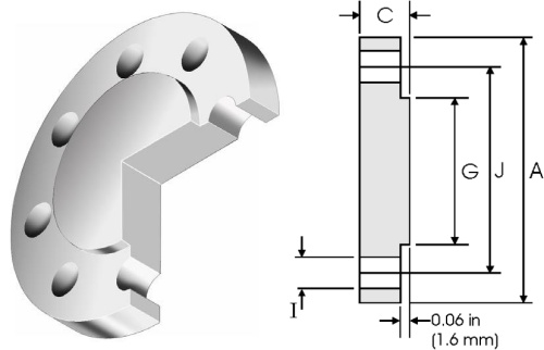
| Norminal Pipe Size | A | C | G | H | I | J | Weight | |
| inch | mm | mm | mm | mm | Holes | mm | mm | kg / piece |
| 1/2 | 21.3 | 88.9 | 11.2 | 35. 10 | 4 | 15.7 | 60.45 | 0.42 |
| 3/4 | 26.7 | 98.6 | 12.7 | 42.9 | 4 | 15.7 | 69.85 | 0.61 |
| 1 | 33.4 | 108 | 14.2 | 50.8 | 4 | 15.7 | 79.25 | 0.86 |
| 11/4 | 42.2 | 117.3 | 15.7 | 63.5 | 4 | 15.7 | 88.9 | 1.17 |
| 11/2 | 48.3 | 127 | 17.5 | 73. 15 | 4 | 15.7 | 98.6 | 1.53 |
| 2 | 60.3 | 152.4 | 19. 10 | 91.9 | 4 | 19.1 | 120.7 | 2.42 |
| 21/2 | 73.0 | 177.8 | 22.4 | 104.6 | 4 | 19.1 | 139.7 | 3.94 |
| 3 | 88.9 | 190.5 | 23.9 | 127 | 4 | 19.1 | 152.4 | 4.93 |
| 31/2 | 101.6 | 215.9 | 23.9 | 139.7 | 8 | 19.1 | 177.8 | 6.17 |
| 4 | 114.3 | 228.6 | 23.9 | 157.2 | 8 | 19.1 | 190.5 | 7.00 |
| 5 | 141.3 | 254 | 23.9 | 185.7 | 8 | 22.4 | 215.9 | 8.63 |
| 6 | 168.3 | 279.4 | 25.4 | 215.9 | 8 | 22.4 | 241.3 | 11.3 |
| 8 | 219.1 | 342.9 | 28.4 | 269.7 | 8 | 22.4 | 298.5 | 19.6 |
| 10 | 273.0 | 406.4 | 30.2 | 323.9 | 12 | 25.4 | 362 | 28.8 |
| 12 | 323.8 | 482.6 | 31.75 | 381 | 12 | 25.4 | 431.8 | 43.2 |
| 14 | 355.6 | 533.4 | 35. 10 | 412.8 | 12 | 28.4 | 476.3 | 58.1 |
| 16 | 406.4 | 596.9 | 36.6 | 469.9 | 16 | 28.4 | 539.8 | 76.0 |
| 18 | 457.2 | 635 | 39.6 | 533.4 | 16 | 31.75 | 577.9 | 93.7 |
| 20 | 508.0 | 698.5 | 42.9 | 584.2 | 20 | 31.75 | 635 | 122 |
| 24 | 609.6 | 812.8 | 47.8 | 692.2 | 20 | 35.1 | 749.3 | 185 |
| Nominal Pipe Size | A | C | G | H | I | J | Weight | |
| inch | mm | mm | mm | mm | Holes | mm | mm | kg / piece |
| 1/2 | 21.3 | 95.2 | 14.2 | 35.1 | 4 | 15.7 | 66.55 | 0.64 |
| 3/4 | 26.7 | 117.3 | 15.7 | 42.9 | 4 | 19 | 82.5 | 1.11 |
| 1 | 33.4 | 123.9 | 17.5 | 50.8 | 4 | 19 | 88.9 | 1.39 |
| 11/4 | 42.2 | 133.3 | 19 | 63.5 | 4 | 19 | 98.5 | 1.79 |
| 11/2 | 48.3 | 155.4 | 20.6 | 73.15 | 4 | 22.3 | 114.3 | 2.66 |
| 2 | 60.3 | 165. 1 | 22.3 | 91.9 | 8 | 19. 10 | 127 | 3.18 |
| 21/2 | 73.0 | 190.5 | 25.4 | 104.6 | 8 | 22.3 | 1.493 | 4.85 |
| 3 | 88.9 | 209.5 | 28.4 | 127 | 8 | 22.3 | 168.1 | 6.81 |
| 31/2 | 101.6 | 228.6 | 30.2 | 139.7 | 8 | 22.3 | 184.1 | 8.71 |
| 4 | 114.3 | 254 | 31.7 | 157.2 | 8 | 22.3 | 200.1 | 11.5 |
| 5 | 141.3 | 279.4 | 35 | 185.7 | 8 | 22.3 | 234.9 | 15.6 |
| 6 | 168.3 | 317.5 | 36.5 | 215.9 | 12 | 22.3 | 269.7 | 20.9 |
| 8 | 219. 1 | 381 | 41.10 | 269.7 | 12 | 25.4 | 330.2 | 34.3 |
| 10 | 273.0 | 444.5 | 47.7 | 323.9 | 16 | 28.4 | 387.3 | 53.3 |
| 12 | 323.8 | 520.7 | 50.8 | 381 | 16 | 31.7 | 450.8 | 78.8 |
| 14 | 355.6 | 584.2 | 53.8 | 412.8 | 20 | 31.7 | 514.3 | 105 |
| 16 | 406.4 | 647.7 | 57.15 | 469.9 | 20 | 35 | 571.5 | 137 |
| 18 | 457.2 | 711.2 | 60.45 | 533.4 | 24 | 35 | 628.6 | 175 |
| 20 | 508.0 | 774.7 | 63.5 | 584.2 | 24 | 35 | 685.8 | 221 |
| 24 | 609.6 | 914.4 | 69.85 | 692.2 | 24 | 41. 10 | 812.8 | 339 |
| Nominal Pipe Size | A | C | G | H | I | J | Weight | |
| inch | mm | mm | mm | mm | Holes | mm | mm | kg / piece |
| 1/2 | 21.3 | 95.2 | 14.2 | 35. 10 | 4 | 15.7 | 66.55 | 0.76 |
| 3/4 | 26.7 | 117.3 | 15.7 | 42.9 | 4 | 19.1 | 82.6 | 1.28 |
| 1 | 33.4 | 123.9 | 17.5 | 50.8 | 4 | 19.1 | 88.9 | 1.60 |
| 11/4 | 42.2 | 133.3 | 20.6 | 63.5 | 4 | 19.1 | 98.6 | 2.23 |
| 11/2 | 48.3 | 155.4 | 22.3 | 73. 15 | 4 | 22.4 | 114.3 | 3.25 |
| 2 | 60.3 | 165.1 | 25.4 | 91.9 | 8 | 19.1 | 127 | 4.15 |
| 21/2 | 73 | 190.5 | 28.4 | 104.6 | 8 | 22.4 | 149.4 | 6.13 |
| 3 | 88.9 | 209.5 | 31.7 | 127 | 8 | 22.4 | 168.1 | 8.44 |
| 31/2 | 101.6 | 228.6 | 35 | 139.7 | 8 | 25.4 | 184.2 | 11.0 |
| 4 | 114.3 | 254 | 35. 10 | 157.2 | 8 | 25.4 | 200.2 | 13.7 |
| 5 | 141.3 | 279.4 | 38. 10 | 185.7 | 8 | 25.4 | 235 | 18.5 |
| 6 | 168.3 | 317.5 | 41. 10 | 215.9 | 12 | 25.4 | 269.7 | 25.5 |
| 8 | 219.1 | 381 | 47.8 | 269.7 | 12 | 28.4 | 330.2 | 42.6 |
| 10 | 273 | 444.5 | 53.8 | 323.9 | 16 | 31.75 | 387.4 | 64.5 |
| 12 | 323.8 | 520.7 | 57. 15 | 381 | 16 | 35.1 | 450.9 | 94.30 |
| 14 | 355.6 | 584.2 | 60.45 | 412.8 | 20 | 35.1 | 514.4 | 124 |
| 16 | 406.4 | 647.7 | 63.5 | 469.9 | 20 | 38.1 | 571.5 | 162 |
| 18 | 457.2 | 711.2 | 66.55 | 533.4 | 24 | 38.1 | 628.7 | 205 |
| 20 | 508 | 774.7 | 69.85 | 584.2 | 24 | 41.1 | 685.8 | 254 |
| 24 | 609.6 | 914.4 | 76.2 | 692.2 | 24 | 47.8 | 812.8 | 386 |
| Nominal Pipe Size | A | C | G | H | I | J | Weight | |
| inch | mm | mm | mm | mm | Holes | mm | mm | kg / piece |
| 1/2 | 21.3 | 95.2 | 14.2 | 35.1 | 4 | 15.7 | 66.55 | 0.76 |
| 3/4 | 26.7 | 117.3 | 15.7 | 42.9 | 4 | 19. 10 | 82.6 | 1.28 |
| 1 | 33.4 | 123.9 | 17.5 | 50.8 | 4 | 19. 10 | 88.9 | 1.60 |
| 11/4 | 42.2 | 133.3 | 20.6 | 63.5 | 4 | 19. 10 | 98.6 | 2.23 |
| 11/2 | 48.3 | 155.4 | 22.3 | 73.15 | 4 | 22.4 | 114.3 | 3.25 |
| 2 | 60.3 | 165. 1 | 25.4 | 91.9 | 8 | 19. 10 | 127 | 4.15 |
| 21/2 | 73 | 190.5 | 28.4 | 104.6 | 8 | 22.4 | 149.4 | 6.13 |
| 3 | 88.9 | 209.5 | 31.7 | 127 | 8 | 22.4 | 168.1 | 8.44 |
| 31/2 | 101.6 | 228.6 | 35 | 139.7 | 8 | 25.4 | 184.2 | 11.0 |
| 4 | 114.3 | 273. 1 | 38.1 | 157.2 | 8 | 25.4 | 215.9 | 17.3 |
| 5 | 141.3 | 330.2 | 44.5 | 185.7 | 8 | 28.4 | 266.7 | 29.4 |
| 6 | 168.3 | 355.6 | 47.8 | 215.9 | 12 | 28.4 | 292.1 | 36.1 |
| 8 | 219. 1 | 419. 1 | 55.6 | 269.7 | 12 | 31.75 | 349.3 | 58.9 |
| 10 | 273 | 508 | 63.5 | 323.9 | 16 | 35. 10 | 431.8 | 97.5 |
| 12 | 323.8 | 558.8 | 66.55 | 381 | 20 | 35. 10 | 489 | 124 |
| 14 | 355.6 | 603.3 | 69.85 | 412.8 | 20 | 38. 10 | 527.1 | 151 |
| 16 | 406.4 | 685.8 | 76.2 | 469.9 | 20 | 41. 10 | 603.3 | 214 |
| 18 | 457.2 | 743 | 82.6 | 533.4 | 20 | 44.5 | 654.1 | 272 |
| 20 | 508.0 | 812.8 | 88.9 | 584.2 | 24 | 44.5 | 723.9 | 349 |
| 24 | 609.6 | 939.8 | 101.6 | 692.2 | 24 | 50.8 | 838.2 | 533 |
| Nominal Pipe Size | A | C | G | H | I | J | Weight | |
| inch | mm | mm | mm | mm | Holes | mm | mm | kg / piece |
| 1/2 | 21.3 | 120.6 | 22.3 | 35. 10 | 4 | 22.3 | 82.5 | 1.77 |
| 3/4 | 26.7 | 130 | 25.4 | 42.9 | 4 | 22.3 | 88.9 | 2.42 |
| 1 | 33.4 | 149.3 | 28.4 | 50.8 | 4 | 25.4 | 101.6 | 3.57 |
| 11/4 | 42.2 | 158.7 | 28.4 | 63.5 | 4 | 25.4 | 111.2 | 4.15 |
| 11/2 | 48.3 | 177.8 | 31.7 | 73. 15 | 4 | 28.4 | 123.9 | 5.75 |
| 2 | 60.3 | 215.9 | 38. 10 | 91.9 | 8 | 25.4 | 165.1 | 10.1 |
| 21/2 | 73 | 244.3 | 41. 10 | 104.6 | 8 | 28.4 | 190.5 | 14.0 |
| 3 | 88.9 | 241.3 | 38. 10 | 127 | 8 | 25.4 | 190.5 | 13.1 |
| 4 | 114.3 | 292.1 | 44.5 | 157.2 | 8 | 31.7 | 234.9 | 26.9 |
| 5 | 141.3 | 349.2 | 50.8 | 185.7 | 8 | 35 | 279.4 | 36.5 |
| 6 | 168.3 | 381 | 55.6 | 215.9 | 12 | 31.7 | 317 | 47.40 |
| 8 | 219.1 | 469.9 | 63.5 | 269.7 | 12 | 38.1 | 393.7 | 82.5 |
| 10 | 273 | 546.1 | 69.85 | 323.9 | 16 | 38.1 | 469.9 | 122 |
| 12 | 323.8 | 609.6 | 79.25 | 381 | 20 | 38.1 | 533.4 | 173 |
| 14 | 355.6 | 641.3 | 85.8 | 412.8 | 20 | 41.1 | 558.8 | 206 |
| 16 | 406.4 | 704.8 | 88.9 | 469.9 | 20 | 44.4 | 615.9 | 259 |
| 18 | 457.2 | 787.4 | 101.6 | 533.4 | 20 | 50.8 | 685.8 | 367 |
| 20 | 508 | 857.2 | 107.9 | 584.2 | 20 | 53.8 | 749.3 | 463 |
| 24 | 609.6 | 1041.4 | 139.7 | 692.2 | 20 | 66.55 | 901.7 | 876 |
| Nominal Pipe Size | A | C | G | H | I | J | Weight | |
| inch | mm | mm | mm | mm | Holes | mm | mm | kg / piece |
| 1/2 | 21.3 | 120.6 | 22.3 | 35.1 | 4 | 22.3 | 82.5 | 1.77 |
| 3/4 | 26.7 | 130 | 25.4 | 42.9 | 4 | 22.3 | 88.9 | 2.42 |
| 1 | 33.4 | 149.3 | 28.4 | 50.8 | 4 | 25.4 | 101.6 | 3.57 |
| 11/4 | 42.2 | 158.7 | 28.4 | 63.5 | 4 | 25.4 | 111.2 | 4.15 |
| 11/2 | 48.3 | 177.8 | 31.7 | 73.15 | 4 | 28.4 | 123.9 | 5.75 |
| 2 | 60.3 | 215.9 | 38.1 | 91.9 | 8 | 25.4 | 165.1 | 10.1 |
| 21/2 | 73 | 244.3 | 41.1 | 104.6 | 8 | 28.4 | 190.5 | 14.0 |
| 3 | 88.9 | 266.7 | 47.7 | 127 | 8 | 31.7 | 203.2 | 19.1 |
| 4 | 114.3 | 311.1 | 53.8 | 157.2 | 8 | 35 | 241.3 | 29.9 |
| 5 | 141.3 | 374.6 | 73.15 | 185.7 | 8 | 41.1 | 292.1 | 58.4 |
| 6 | 168.3 | 393.7 | 82.5 | 215.9 | 12 | 38.1 | 317.5 | 71.8 |
| 8 | 219. 1 | 482.6 | 91.9 | 269.7 | 12 | 44.4 | 393.7 | 122 |
| 10 | 273 | 584.2 | 107.9 | 323.9 | 12 | 50.8 | 482.6 | 210 |
| 12 | 323.8 | 673. 1 | 123.9 | 381 | 16 | 53.8 | 571.5 | 316 |
| 14 | 355.6 | 749.3 | 133.3 | 412.8 | 16 | 60.45 | 635 | 420 |
| 16 | 406.4 | 825.5 | 146 | 469.9 | 16 | 66.55 | 704.8 | 558 |
| 18 | 457.2 | 914.4 | 162 | 533.4 | 16 | 73. 15 | 774.7 | 760 |
| 20 | 508 | 984.2 | 177.8 | 584.2 | 16 | 79.25 | 831.8 | 965 |
| 24 | 609.6 | 1168.4 | 203.2 | 692.2 | 16 | 91.9 | 990.6 | 1558 |
| Nominal Pipe Size | A | C | G | H | I | J | Weight | |
| inch | mm | mm | mm | mm | Holes | mm | mm | kg / piece |
| 1/2 | 21.3 | 133.4 | 30.2 | 35. 10 | 4 | 22.4 | 88.9 | 2.99 |
| 3/4 | 26.7 | 139.7 | 31.7 | 42.9 | 4 | 22.4 | 95.3 | 3.50 |
| 1 | 33.4 | 158.8 | 35. 10 | 50.8 | 4 | 25.4 | 108 | 4.96 |
| 11/4 | 42.2 | 184.2 | 38. 10 | 63.5 | 4 | 28.4 | 130 | 7.35 |
| 11/2 | 48.3 | 203.2 | 44.5 | 73. 15 | 4 | 31.75 | 146.1 | 10.4 |
| 2 | 60.3 | 235 | 50.8 | 91.9 | 8 | 28.4 | 171.5 | 15.6 |
| 21/2 | 73 | 266.7 | 57. 15 | 104.6 | 8 | 31.75 | 196.9 | 22.6 |
| 3 | 88.9 | 304.8 | 66.55 | 127 | 8 | 35.1 | 228.6 | 34.8 |
| 4 | 114.3 | 355.6 | 76.2 | 157.2 | 8 | 41.1 | 273.1 | 53.9 |
| 5 | 141.3 | 419.1 | 91.9 | 185.7 | 8 | 47.88 | 323.9 | 90.8 |
| 6 | 168.3 | 482.6 | 108 | 215.9 | 8 | 53.8 | 368.3 | 141 |
| 8 | 219.1 | 552.5 | 127 | 269.7 | 12 | 53.8 | 438.2 | 214 |
| 10 | 273 | 673.1 | 165.1 | 323.9 | 12 | 66.55 | 539.8 | 411 |
| 12 | 323.8 | 762 | 184.2 | 381 | 12 | 73.15 | 619.3 | 592 |
Due to their reliable sealing performance and standardized design, ASME B16.5 blind flanges are used across virtually every industrial sector.
Used on pressure vessels like reactors, storage tanks, and heat exchangers to seal process openings or manholes that are not permanently connected.
Used to temporarily or permanently cap the end of a pipe branch reserved for future expansion.
Installed to seal off a piping system after construction or repair, allowing hydrostatic or pneumatic tests to verify system strength and tightness.
During equipment maintenance, a blind flange is installed downstream of a shut-off valve. This creates a positive, absolute physical isolation, preventing media from leaking past the valve and entering the work area. It serves as the "final line of defense" for the safety of maintenance personnel.
With its simple structure, robust pressure resistance, and standardized dimensions, the ASME B16.5 blind flange plays a critical role in industrial piping systems. Understanding its dimensional specifications and pressure classes is essential for ensuring the safe and reliable operation of your piping system.
