


Views: 10 Author: Site Editor Publish Time: 2026-04-30 Origin: Site


In industrial pipeline system construction, forged flanges are important components for connecting pipes, valves, and equipment to ensure reliable system operation. Shanghai Zhucheng Pipe Fitting Manufacturing Co., Ltd., as a professional supplier of ASME B16.5 forged flanges in China, can provide domestic and international customers with forged flange products in various sizes, types, and materials. The Slip-On Flange (SO Flange) is one of the most widely used types of ASME B16.5 forged flanges. Due to its simple structure, easy installation, and low cost, it has become an important part of low-pressure, normal-temperature industrial piping systems.
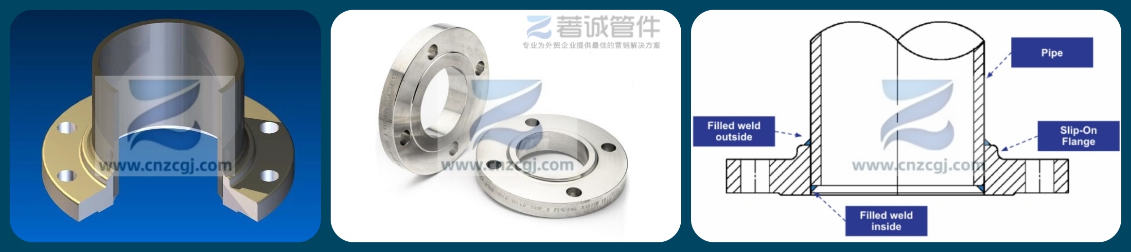
The Slip-On flange has a simple structure. Its main body is disc-shaped, with a center bore matching the pipe size. Multiple bolt holes are evenly distributed around the flange disc, used with bolts, nuts, and gaskets for connection.
The Slip-On flange has a short neck at the connection between the flange disc and the pipe, which improves the flange’s rigidity and load-carrying capacity. Common sealing faces are Flat Face (FF) and Raised Face (RF). The neck is short, and when welding to the pipe, the pipe end is flush with the flange sealing face, with the weld located on the outside of the flange.
The Slip-On flange (SO flange) is one of the most common flange types in piping systems. Its core features are simple structure, easy installation, and low cost. The flange bore is slightly larger than the pipe outer diameter, allowing the pipe to “slip on” into the flange (hence the name). After installation, fillet welds are made on both the inside and outside of the flange. This provides pipe connection and sealing, and is widely used in medium-to-low pressure, normal-temperature, or low-temperature fluid transport applications.
Easy installation: Simple welding process, less demanding on pipe cutting accuracy and alignment, high on-site construction efficiency.
Cost-effective: Simple structure, low manufacturing cost, suitable for batch purchasing and large-scale application.
Wide applicability: Can be used with carbon steel pipes, stainless steel pipes, and many other materials. Common in water treatment, HVAC, low-pressure steam, compressed air systems, and many chemical processes.
Weak pressure resistance: Due to its structural characteristics, its pressure resistance is lower than that of weld neck flanges. Not recommended for applications with large pressure fluctuations, severe vibration, or high temperature and high pressure.
ANSI stands for the American National Standards Institute, founded in 1918. At that time, many U.S. companies and technical groups had begun standardization work, but due to lack of coordination, there were many conflicts and problems. To improve efficiency, hundreds of technical societies, associations, and groups felt the need to establish a specialized standardization body and create unified general standards.
ASME generally refers to the American Society of Mechanical Engineers. ASME B16.5 is a standard for pipe flanges and flanged fittings recommended by ASME. It is an authoritative and widely used international standard and also meets ANSI requirements, so it is also called the ANSI B16.5 flange standard.
Simply put, ANSI is a national coordinating body in the U.S., while ASME is an organization that develops specific technical standards. The relationship is one of recognition.
ANSI (American National Standards Institute): A coordinator and recognizer of the U.S. voluntary standards system. It does not develop standards itself but provides a platform and rules for professional organizations (such as ASME, ASTM, API) to develop standards and recognizes them as “American National Standards.”
ASME (American Society of Mechanical Engineers): A professional technical organization and an ANSI-recognized standards developer. It drafts and publishes specific engineering standards. ASME B16.5 is also an American National Standard recognized by ANSI.
Therefore, the standard number “ANSI/ASME B16.5” indicates that the standard was developed by ASME and approved by ANSI as a national standard.
ASME B16.5 is published by the American Society of Mechanical Engineers for “Pipe Flanges and Flanged Fittings” and is one of the most widely used flange standards in global petrochemical, power, and other industries. It includes:
Flange Type | Connection Method | Features & Typical Applications |
Weld Neck (WN) | Butt weld to pipe | Long tapered neck, high strength, low stress concentration. Suitable for high pressure, high temperature, and severe conditions. |
Slip-On (SO) | Slides over pipe end, welded | Easy installation, low cost. Used in medium-to-low pressure piping systems. |
Blind (BL) | No center hole | Used to close pipe ends, for pressure testing, or as manhole covers on equipment. |
Socket Weld (SW) | Pipe inserted into socket | Used for small bore (NPS 1/2 to NPS 3) high-pressure pipes. |
Threaded (TH) | Internal threads connect to external pipe threads | Used where welding is not possible, such as galvanized pipes or explosive environments. |
Lap Joint (LJ) | Slides over a stub end | Flange material can differ from pipe material (e.g., corrosion-resistant lined pipes), easy to disassemble and clean. |
Size range: 1/2" to 24"
Pressure classes: Class 150, 300, 400, 600, 900, 1500, 2500
Materials: Forged carbon steel (ASTM A105), alloy steel (ASTM A182 F11/F12), stainless steel (ASTM A182 F304/F316), etc.
Core value of ASME B16.5: Ensures safe sealing and strength interchangeability of flanges under specified pressure and temperature. A flange marked “ASME B16.5 SO” means its design, manufacturing, and inspection comply with this standard.
ASME B16.5 specifies strict dimensions for Slip-On flanges, mainly including:
Flange outside diameter (O): Increases with pressure class and nominal pipe size (NPS)
Bolt circle diameter (PCD): Determines bolt alignment with the mating flange
Flange inside diameter (B): Slightly larger than pipe OD (e.g., for NPS 4″ Sch40 pipe, flange bore approx. 116.1 mm)
Flange thickness (T): Increases with Class rating
Sealing face height (approx. 2mm for RF)
Neck diameter and fillet radius
Example: Class 150, NPS 4″, RF face SO flange (units: mm):
Flange OD: 228.6
Bolt circle diameter: 190.5
Number of bolt holes: 8
Bolt hole diameter: 19
Flange thickness: 22.3
Flange bore: approx. 116.1 (matching pipe)
The standard clearly provides all key dimensions for each pressure class and size — no calculations needed.
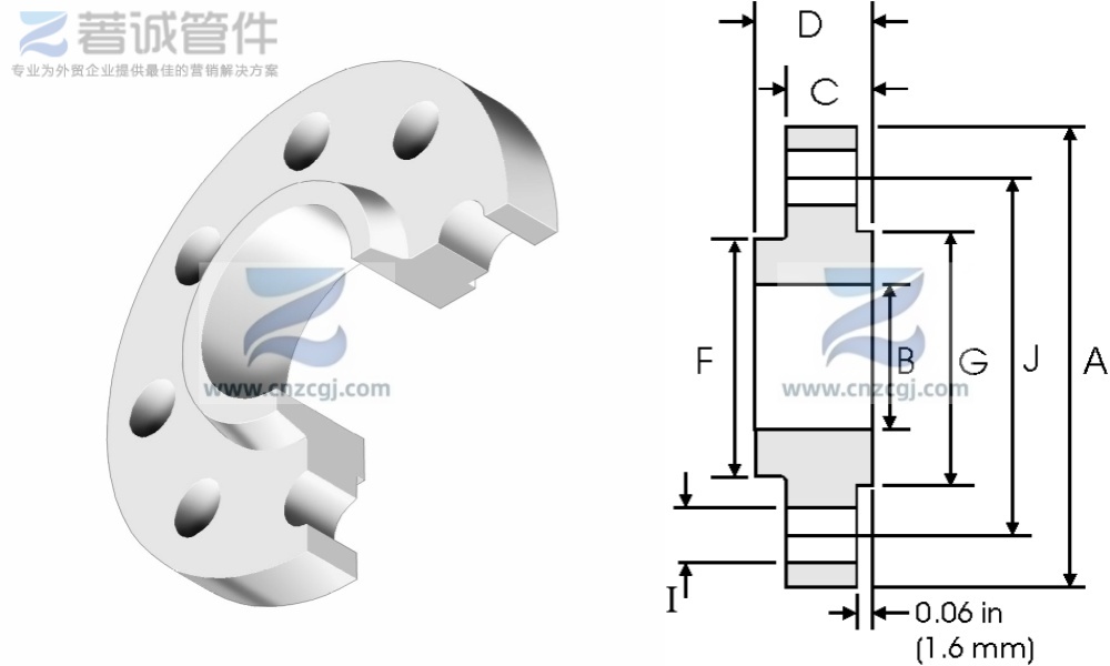
| Nominal Pipe Size | A | B | C | D | F | G | H | I | J | Weight | |
| inch | mm | mm | mm | mm | mm | mm | mm | Holes | mm | mm | kg / piece |
| 1/2 | 21.3 | 88.9 | 22.4 | 11.2 | 15.7 | 30.2 | 35.1 | 4 | 15.7 | 60.45 | 0.39 |
| 3/4 | 26.7 | 98.6 | 27.7 | 12.7 | 15.7 | 38. 10 | 42.9 | 4 | 15.7 | 69.85 | 0.56 |
| 1 | 33.4 | 108 | 34.5 | 14.2 | 17.5 | 49.3 | 50.8 | 4 | 15.7 | 79.25 | 0.78 |
| 11/4 | 42.2 | 117.3 | 43.2 | 15.7 | 20.6 | 58.7 | 63.5 | 4 | 15.7 | 88.9 | 1.03 |
| 11/2 | 48.3 | 127 | 49.5 | 17.5 | 22.4 | 65 | 73.15 | 4 | 15.7 | 98.6 | 1.32 |
| 2 | 60.3 | 152.4 | 62 | 19.1 | 25.4 | 77.7 | 91.9 | 4 | 19.1 | 120.7 | 2.06 |
| 21/2 | 73 | 177.8 | 74.7 | 22.4 | 28.4 | 90.4 | 104.6 | 4 | 19.1 | 139.7 | 3.28 |
| 3 | 88.9 | 190.5 | 90.7 | 23.9 | 30.2 | 108 | 127 | 4 | 19.1 | 152.4 | 3.85 |
| 31/2 | 101.6 | 215.9 | 103.4 | 23.9 | 31.75 | 122.2 | 139.7 | 8 | 19.1 | 177.8 | 4.81 |
| 4 | 114.3 | 228.6 | 116.1 | 23.9 | 33.3 | 134.9 | 157.2 | 8 | 19.1 | 190.5 | 5.30 |
| 5 | 141.3 | 254 | 143.8 | 23.9 | 36.6 | 163.6 | 185.7 | 8 | 22.4 | 215.9 | 6.07 |
| 6 | 168.3 | 279.4 | 170.7 | 25.4 | 39.6 | 192 | 215.9 | 8 | 22.4 | 241.3 | 7.45 |
| 8 | 219.1 | 342.9 | 221.5 | 28.4 | 44.5 | 246.1 | 269.7 | 8 | 22.4 | 298.5 | 12.1 |
| 10 | 273 | 406.4 | 276.3 | 30.2 | 49.3 | 304.8 | 323.9 | 12 | 25.4 | 362 | 16.5 |
| 12 | 323.8 | 482.6 | 327.1 | 31.75 | 55.6 | 365.3 | 381 | 12 | 25.4 | 431.8 | 26.2 |
| 14 | 355.6 | 533.4 | 359.1 | 35.1 | 57.15 | 400.1 | 412.8 | 12 | 28.4 | 476.3 | 34.6 |
| 16 | 406.4 | 596.9 | 410.5 | 36.6 | 63.5 | 457.2 | 469.9 | 16 | 28.4 | 539.8 | 44.8 |
| 18 | 457.2 | 635 | 461.8 | 39.6 | 68.3 | 505 | 533.4 | 16 | 31.75 | 577.9 | 48.9 |
| 20 | 508 | 698.5 | 513.1 | 42.9 | 73.15 | 558.8 | 584.2 | 20 | 31.75 | 635 | 61.9 |
| 24 | 609.6 | 812.8 | 616 | 47.8 | 82.6 | 663.4 | 692.2 | 20 | 35.1 | 749.3 | 86.9 |
| Nominal Pipe Size | A | B | C | D | F | G | H | I | J | Weight | |
| inch | mm | mm | mm | mm | mm | mm | mm | Holes | mm | mm | kg / piece |
| 1/2 | 21.3 | 95.2 | 22.4 | 14.2 | 22.4 | 38.1 | 35.1 | 4 | 15.7 | 66.55 | 0.64 |
| 3/4 | 26.7 | 117.3 | 27.7 | 15.7 | 25.4 | 47.7 | 42.9 | 4 | 19.1 | 82.5 | 1. 12 |
| 1 | 33.4 | 123.9 | 34.5 | 17.5 | 26.9 | 53.8 | 50.8 | 4 | 19.1 | 88.9 | 1.36 |
| 11/4 | 42.2 | 133.3 | 43.2 | 19 | 26.9 | 63.5 | 63.5 | 4 | 19.1 | 98.6 | 1.68 |
| 11/2 | 48.3 | 155.4 | 49.5 | 20.6 | 30.2 | 69.85 | 73.15 | 4 | 22.4 | 114.3 | 2.49 |
| 2 | 60.3 | 165.1 | 62 | 22.3 | 33.2 | 84 | 91.9 | 8 | 19.1 | 127 | 2.87 |
| 21/2 | 73 | 190.5 | 74.7 | 25.4 | 38.1 | 100 | 104.6 | 8 | 22.4 | 149.4 | 4.32 |
| 3 | 88.9 | 209.5 | 90.7 | 28.4 | 42.9 | 117.3 | 127 | 8 | 22.4 | 168.1 | 5.85 |
| 31/2 | 101.6 | 228.6 | 103.4 | 30.2 | 44.4 | 133.3 | 139.7 | 8 | 22.4 | 184.2 | 7.34 |
| 4 | 114.3 | 254 | 116.1 | 31.7 | 47.7 | 146 | 157.2 | 8 | 22.4 | 200.1 | 9.61 |
| 5 | 141.3 | 279.4 | 143.8 | 35 | 50.8 | 177.8 | 185.7 | 8 | 22.4 | 234.9 | 12.3 |
| 6 | 168.3 | 317.5 | 170.7 | 36.5 | 52.3 | 206.2 | 215.9 | 12 | 22.4 | 269.7 | 15.6 |
| 8 | 219. 1 | 381 | 221.5 | 41.1 | 61.9 | 260.3 | 269.7 | 12 | 25.4 | 330.2 | 24.2 |
| 10 | 273 | 444.5 | 276.3 | 47.7 | 66.55 | 320.5 | 323.9 | 16 | 28.4 | 387.3 | 34.1 |
| 12 | 323.8 | 520.7 | 327.1 | 50.8 | 73.15 | 374.6 | 381 | 16 | 31.7 | 450.8 | 49.8 |
| 14 | 355.6 | 584.2 | 359.1 | 53.8 | 76.2 | 425.4 | 412.8 | 20 | 31.7 | 514.4 | 69.9 |
| 16 | 406.4 | 647.7 | 410.5 | 57.15 | 82.5 | 482.6 | 469.9 | 20 | 35 | 571.5 | 88.1 |
| 18 | 457.2 | 711.2 | 461.8 | 60.45 | 88.9 | 533.4 | 533.4 | 24 | 35 | 628.7 | 109 |
| 20 | 508 | 774.7 | 513.1 | 63.5 | 95.2 | 587.2 | 584.2 | 24 | 35 | 685.8 | 134 |
| 24 | 609.6 | 914.4 | 616 | 69.85 | 106.4 | 701.5 | 692.2 | 24 | 41 | 812.8 | 201 |
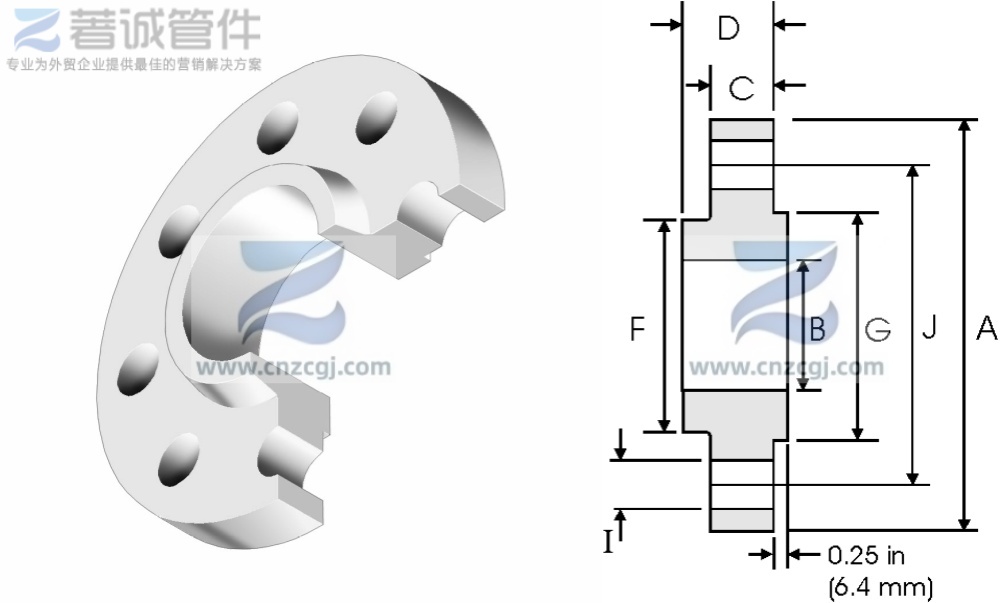
| Nominal Pipe Size | A | B | C | D | F | G | H | I | J | Weight | |
| inch | mm | mm | mm | mm | mm | mm | mm | Holes | mm | mm | kg / piece |
| 1/2 | 21.3 | 95.3 | 22.4 | 14.2 | 22.4 | 38.1 | 35. 10 | 4 | 15.7 | 66.55 | 0.74 |
| 3/4 | 26.7 | 117.3 | 27.7 | 15.7 | 25.4 | 47.7 | 42.9 | 4 | 19.1 | 82.5 | 1.27 |
| 1 | 33.4 | 124 | 34.5 | 17.5 | 26.9 | 53.8 | 50.8 | 4 | 19.1 | 88.9 | 1.52 |
| 11/4 | 42.2 | 133.4 | 43.2 | 20.6 | 28.4 | 63.5 | 63.5 | 4 | 19.1 | 98.6 | 2.03 |
| 11/2 | 48.3 | 155.4 | 49.5 | 22.4 | 31.75 | 69.85 | 73. 15 | 4 | 22.4 | 114.3 | 2.96 |
| 2 | 60.3 | 165.1 | 62 | 25.4 | 36.6 | 84 | 91.9 | 8 | 19.1 | 127 | 3.62 |
| 21/2 | 73 | 190.5 | 74.7 | 28.4 | 41.1 | 100 | 104.6 | 8 | 22.4 | 149.4 | 5.28 |
| 3 | 88.9 | 209.6 | 90.7 | 31.75 | 46 | 117.3 | 127 | 8 | 22.4 | 168. 1 | 7.00 |
| 31/2 | 101.6 | 228.6 | 103.4 | 35.1 | 49.3 | 133.3 | 139.7 | 8 | 25.4 | 184.2 | 8.84 |
| 4 | 114.3 | 254 | 116.1 | 35.1 | 50.8 | 146 | 157.2 | 8 | 25.4 | 200. 1 | 11. 1 |
| 5 | 141.3 | 279.4 | 143.8 | 38.1 | 53.8 | 177.8 | 185.7 | 8 | 25.4 | 234.9 | 13.9 |
| 6 | 168.3 | 317.5 | 170.7 | 41.1 | 57.15 | 206.2 | 215.9 | 12 | 25.4 | 269.7 | 18.3 |
| 8 | 219.1 | 381 | 221.5 | 47.8 | 68.3 | 260.3 | 269.7 | 12 | 28.4 | 330.2 | 28.6 |
| 10 | 273 | 444.5 | 276.3 | 53.8 | 73.15 | 320.5 | 323.9 | 16 | 31.75 | 387.3 | 39.2 |
| 12 | 323.8 | 520.7 | 327. 1 | 57.15 | 79.25 | 374.6 | 381 | 16 | 35.1 | 450.8 | 57.0 |
| 14 | 355.6 | 584.2 | 359. 1 | 60.05 | 84.1 | 425.4 | 412.8 | 20 | 35.1 | 514.4 | 79.1 |
| 16 | 406.4 | 647.7 | 410.5 | 63.5 | 93.7 | 482.6 | 469.9 | 20 | 38.1 | 571.5 | 101 |
| 18 | 457.2 | 711.2 | 461.8 | 66.55 | 98.6 | 533.4 | 533.4 | 24 | 38.1 | 628.7 | 123 |
| 20 | 508 | 774.7 | 513. 1 | 69.85 | 101.6 | 587.2 | 584.2 | 24 | 41.1 | 685.8 | 146 |
| 24 | 609.6 | 914.4 | 616 | 76.2 | 114.3 | 701.5 | 692.2 | 24 | 47.8 | 812.8 | 219 |
| Nominal Pipe Size | A | B | C | D | F | G | H | I | J | Weight | |
| inch | mm | mm | mm | mm | mm | mm | mm | Holes | mm | mm | kg / piece |
| 1/2 | 21.3 | 95.3 | 22.4 | 14.2 | 22.4 | 38.1 | 35.1 | 4 | 15.7 | 66.55 | 0.74 |
| 3/4 | 26.7 | 117.3 | 27.7 | 15.7 | 25.4 | 47.8 | 42.9 | 4 | 19.1 | 82.6 | 1.27 |
| 1 | 33.4 | 124 | 34.5 | 17.5 | 26.9 | 53.8 | 50.8 | 4 | 19.1 | 88.9 | 1.52 |
| 11/4 | 42.2 | 133.4 | 43.2 | 20.6 | 28.4 | 63.5 | 63.5 | 4 | 19.1 | 98.6 | 2.03 |
| 11/2 | 48.3 | 155.4 | 49.5 | 22.4 | 31.75 | 69.85 | 73.15 | 4 | 22.4 | 114.3 | 2.96 |
| 2 | 60.3 | 165.1 | 62 | 25.4 | 36.6 | 84.1 | 91.9 | 8 | 19.1 | 127 | 3.62 |
| 21/2 | 73 | 190.5 | 74.7 | 28.4 | 41.1 | 100.1 | 104.6 | 8 | 22.4 | 149.4 | 5.28 |
| 3 | 88.9 | 209.6 | 90.7 | 31.75 | 46 | 117.3 | 127 | 8 | 22.4 | 168.1 | 7.00 |
| 31/2 | 101.6 | 228.6 | 103.4 | 35.1 | 49.3 | 133.4 | 139.7 | 8 | 25.4 | 184.2 | 8.84 |
| 4 | 114.3 | 273.1 | 116.1 | 38.1 | 53.8 | 152.4 | 157.2 | 8 | 25.4 | 215.9 | 14.5 |
| 5 | 141.3 | 330.2 | 143.8 | 44.5 | 60.45 | 189 | 185.7 | 8 | 28.4 | 266.7 | 24.4 |
| 6 | 168.3 | 355.6 | 170.7 | 47.8 | 66.55 | 222.3 | 215.9 | 12 | 28.4 | 292.1 | 28.7 |
| 8 | 219. 1 | 419.1 | 221.5 | 55.6 | 76.2 | 273.1 | 269.7 | 12 | 31.75 | 349.3 | 43.4 |
| 10 | 273 | 508 | 276.3 | 63.5 | 85.9 | 342.9 | 323.9 | 16 | 35.1 | 431.8 | 70.3 |
| 12 | 323.8 | 558.8 | 327.1 | 66.55 | 91.9 | 400.1 | 381 | 20 | 35.1 | 489 | 84.2 |
| 14 | 355.6 | 603.3 | 359.1 | 69.85 | 93.7 | 431.8 | 412.8 | 20 | 38.1 | 527.1 | 98.7 |
| 16 | 406.4 | 685.8 | 410.5 | 76.2 | 106.4 | 495.3 | 469.9 | 20 | 41.1 | 603.3 | 142 |
| 18 | 457.2 | 743 | 461.8 | 82.6 | 117.3 | 546.1 | 533.4 | 20 | 44.5 | 654.1 | 173 |
| 20 | 508 | 812.8 | 513.1 | 88.9 | 127 | 609.6 | 584.2 | 24 | 44.5 | 723.9 | 220 |
| 24 | 609.6 | 939.8 | 616 | 101.6 | 139.7 | 717.6 | 692.2 | 24 | 50.8 | 838.2 | 312 |
| Nominal Pipe Size | A | B | C | D | F | G | H | I | J | Weight | |
| inch | mm | mm | mm | mm | mm | mm | mm | Holes | mm | mm | kg / piece |
| 1/2 | 21.3 | 120.6 | 22.4 | 22.4 | 31.7 | 38. 10 | 35.1 | 4 | 22.4 | 82.5 | 1.74 |
| 3/4 | 26.7 | 130 | 27.7 | 25.4 | 35 | 44.4 | 42.9 | 4 | 22.4 | 88.9 | 2.34 |
| 1 | 33.4 | 149.3 | 34.5 | 28.4 | 41.1 | 52.3 | 50.8 | 4 | 25.4 | 101.6 | 3.44 |
| 11/4 | 42.2 | 158.7 | 43.2 | 28.4 | 41.1 | 63.5 | 63.5 | 4 | 25.4 | 111.2 | 3.91 |
| 11/2 | 48.3 | 177.8 | 49.5 | 31.7 | 44.5 | 69.85 | 73.15 | 4 | 28.4 | 123.9 | 5.36 |
| 2 | 60.3 | 215.9 | 62 | 38.1 | 57.15 | 104.6 | 91.9 | 8 | 25.4 | 165.1 | 9.85 |
| 21/2 | 73 | 244.3 | 74.7 | 41.1 | 63.5 | 123.9 | 104.6 | 8 | 28.4 | 190.5 | 13.7 |
| 3 | 88.9 | 241.3 | 90.7 | 38.1 | 53.8 | 127 | 127 | 8 | 25.4 | 190.5 | 11.6 |
| 4 | 114.3 | 292.1 | 116.1 | 44.4 | 69.85 | 158.7 | 157.2 | 8 | 31.7 | 234.9 | 19.7 |
| 5 | 141.3 | 349.2 | 143.8 | 50.8 | 79.25 | 190.5 | 185.7 | 8 | 35 | 279.4 | 31.9 |
| 6 | 168.3 | 381 | 170.7 | 55.6 | 85.8 | 234.9 | 215.9 | 12 | 31.7 | 317.5 | 41.1 |
| 8 | 219.1 | 469.9 | 221.5 | 63.5 | 101.6 | 298.4 | 269.7 | 12 | 38.1 | 393.7 | 70.7 |
| 10 | 273 | 546.1 | 276.3 | 69.85 | 107.9 | 368.3 | 323.9 | 16 | 38.1 | 469.9 | 101 |
| 12 | 323.8 | 609.6 | 327.1 | 79.25 | 117.3 | 419.1 | 381 | 20 | 38.1 | 533.4 | 133 |
| 14 | 355.6 | 641.3 | 359.1 | 85.8 | 130 | 450.8 | 412.8 | 20 | 41.1 | 558.8 | 153 |
| 16 | 406.4 | 704.8 | 410.5 | 88.9 | 133.3 | 508 | 469.9 | 20 | 44.4 | 615.9 | 185 |
| 18 | 457.2 | 787.4 | 461.8 | 101.6 | 152.4 | 565.1 | 533.4 | 20 | 50.8 | 685.8 | 258 |
| 20 | 508 | 857.2 | 513.1 | 107.9 | 158.7 | 622.3 | 584.2 | 20 | 53.8 | 749.3 | 317 |
| 24 | 609.6 | 1041.4 | 616 | 139.7 | 203.2 | 749.3 | 692.2 | 20 | 66.55 | 901.7 | 606 |
| Nominal Pipe Size | A | B | C | D | F | G | H | I | J | Weight | |
| inch | mm | mm | mm | mm | mm | mm | mm | Holes | mm | mm | kg / piece |
| 1/2 | 21.3 | 120.6 | 22.4 | 22.4 | 31.7 | 38.1 | 35.1 | 4 | 22.4 | 82.5 | 1.74 |
| 3/4 | 26.7 | 130 | 27.7 | 25.4 | 35 | 44.4 | 42.9 | 4 | 22.4 | 88.9 | 2.34 |
| 1 | 33.4 | 149.3 | 34.5 | 28.4 | 41.1 | 52.3 | 50.8 | 4 | 25.4 | 101.6 | 3.44 |
| 11/4 | 42.2 | 158.7 | 43.2 | 28.4 | 41.1 | 63.5 | 63.5 | 4 | 25.4 | 111.2 | 3.91 |
| 11/2 | 48.3 | 177.8 | 49.5 | 31.7 | 44.5 | 69.85 | 73.15 | 4 | 28.4 | 123.9 | 5.36 |
| 2 | 60.3 | 215.9 | 62 | 38.1 | 57.15 | 104.6 | 91.9 | 8 | 25.4 | 165.1 | 9.85 |
| 21/2 | 73 | 244.3 | 74.7 | 41.1 | 63.5 | 123.9 | 104.6 | 8 | 28.4 | 190.5 | 13.7 |
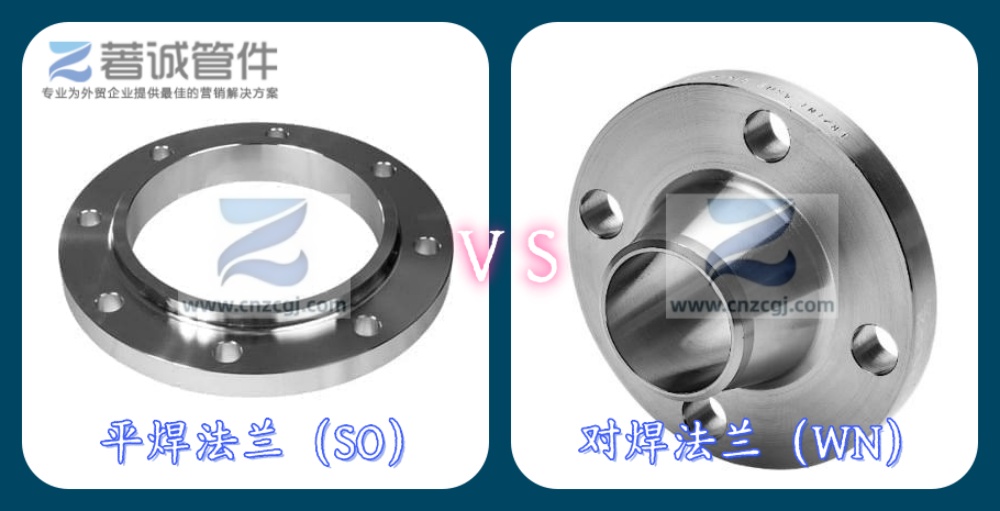
In actual industrial piping design and selection, Slip-On (SO) and Weld Neck (WN) flanges are often compared.
Comparison Item | Slip-On (SO) | Weld Neck (WN) |
Welding method | Fillet welds (inside & outside) | Butt weld (pipe to flange neck) |
Structural strength | Moderate, suitable for low pressure | High, suitable for high pressure & high temperature |
Fatigue resistance | Poor, not for severe vibration | Good, smooth stress transition |
Installation difficulty | Simple, low alignment requirement | Requires precise alignment and bevel preparation |
Cost | Lower | Higher (material & machining) |
Application range | Class 150~400, normal/low pressure | Class 150~2500, high temp/high pressure, critical services |
For general water, air, or oil lines without severe cyclic loads, ASME B16.5 Slip-On flanges are recommended for cost-effectiveness. For high temperature/pressure, toxic media, or critical equipment connections, Weld Neck flanges should be selected.
ASME B16.5 Slip-On flanges are typically manufactured by forging: the steel billet is heated, forged into a flange blank, then machined into the finished product.
Dense structure, no casting defects (porosity, shrinkage)
Better mechanical properties than cast flanges, especially impact toughness and fatigue resistance
Suitable for carbon steel, stainless steel, alloy steel, etc.
High precision of sealing face, low leakage risk
Petrochemical industry: atmospheric/vacuum distillation, catalytic cracking, tank piping
Industrial gases: nitrogen, compressed air lines
Municipal engineering: water supply, heating networks
Water treatment: sewage, reclaimed water pipes
Marine piping systems (some low-pressure areas)
ASME B16.5 Slip-On flanges, with their standardized design, easy installation, and cost advantages, are one of the most widely used flange types in industrial piping. For selection, just confirm pressure class (Class), nominal pipe size (NPS), sealing face type (RF/FF), and material — then standard parts can be matched quickly. For non-high-temperature, non-high-pressure, and no severe cyclic load conditions, ASME B16.5 SO flanges provide safe, economical, and efficient connections for industrial pipelines.
