

Views: 14 Author: Site Editor Publish Time: 2025-10-29 Origin: Site


In the connection system of industrial pipeline systems, welding neck flanges are key components for achieving reliable connections between pipelines and equipment, as well as between pipelines. Welding neck flanges that comply with ASME B16.47 standards, with their excellent structural strength, wide specification coverage, and strict quality control, have become an important solution for high-pressure and large-diameter pipeline connections in major industrial fields such as petroleum, chemical, and energy, providing solid guarantees for the safe operation of pipeline systems.

From the appearance, the ASME B16.47 welding neck flange has a disc-shaped structure as a whole, mainly composed of three parts: flange ring, neck, and welding end. Multiple bolt holes are evenly distributed on the flange ring, which are used to connect with the matching flange through bolts and form a sealed space; The neck design is conical or cylindrical, which can effectively disperse the stress caused by the pressure of the pipeline medium and enhance the overall bearing capacity of the flange; The welding end is equipped with a standard groove (usually 37.5 °± 2.5 °), which can be docked with the end of the pipeline and form a firm connection structure through welding.
According to the different forms of sealing surfaces, ASME B16.47 welding neck flanges can be divided into protruding surface (RF), concave convex surface (MFM), tenon groove surface (TG) and other types. Among them, protruding surface flanges are the most widely used in conventional working conditions due to their simple processing and stable sealing performance; Concave convex surface and mortise and tenon groove flange are suitable for high-pressure and leak prone harsh scenarios, improving sealing reliability through surface to surface bonding.
ASME B16.47 welding neck flanges provide detachable, leak-proof connections for pipelines, valves, and equipment. They withstand axial/radial forces, torque, and harsh conditions like high temperature and pressure. Ideal for maintenance and repairs, they enable quick connections in oil pipelines and secure reactor vessels in chemical plants.
ASME B16.47, "Large Diameter Steel Flanges," is a global standard for large-diameter, high-pressure steel welding neck flanges. It comprises two series: Series A (based on API 605, primarily for oil and gas) and Series B (based on MSS SP-44, with broader application), which share unified quality control despite differences in dimensions and pressure ratings.
The standard covers flanges from NPS 26 to NPS 60 and pressure classes 150 to 1500, accommodating materials like carbon steel, stainless steel, and alloy steel. It addresses the connection needs of large-diameter pipelines (e.g., DN 650 to DN 1500) under high-pressure and high-temperature conditions, filling a gap left by standards like ASME B16.5.
Regulatory requirements include strict dimensional tolerances, mandatory mechanical tests (tensile, impact, hardness), and quality inspections (visual, NDT, surface roughness). High-pressure flanges may also require hydrostatic testing to ensure safety and consistency.
Types | Weld Neck Flange(WN)、Blind Flange(BL) |
Sealing Suface | RF, FF, RTJ |
Size | 26" - 60" / DN650 - DN1500 |
Standard | ASME B16.47 A/B |
Although ASME B16.47 and ASME B16.5 belong to the same butt welding flange standard, there are significant differences in applicable scenarios, specification ranges, and technical requirements. The specific differences are as follows:
ASME B16.5 mainly targets small-diameter flanges, covering nominal sizes from 1/2 inch to 24 inches, and is suitable for small and medium-sized pipeline systems;
ASME B16.47 focuses on large-diameter flanges, covering NPS 26 to NPS 60, specifically designed for large-diameter industrial pipelines. The two complement each other in size and meet the connection needs of pipeline systems of different scales.
ASME B16.5 standard uses seven pressure levels: Class 150, 300, 400, 600, 900, 1500, 2500, etc;
ASME B16.47 standard is applicable to pressure classes seriesA , including Class 150, 300, 400, 600, 900, and other five grades;
seriesB : Class75、 There are six levels: 150, 300, 400, 600, 900, etc.
The ASME B16.5 standard includes six types of flanges: butt welding flange (WN FLANGE), flat welding flange (SO FLANGE), socket flange (SW FLANGE), threaded flange (TH FLANGE), blind flange (BL FLANGE), and loose flange (LAPJ FLANGE).
The ASME B16.47 standard includes two types of flanges: butt welded flanges (WN FLANGE) and blind flanges (BL FALNGE).
ASME B16.5 is an independently developed universal flange standard with a wide range of applications, covering multiple industries such as petroleum, chemical, power, municipal, etc;
ASME B16.47 is divided into two versions, A and B. The A version is based on API 605 standard, which is more in line with the high-pressure and high-risk working conditions requirements of the oil and gas industry. The B version is based on MSS SP-44 standard, which is suitable for general industrial fields such as chemical and energy, and has stronger industry specificity.
ASME B16.47 flanges have larger dimensions, thicker neck designs, and some specifications have reinforcing ribs to enhance stress resistance; In terms of installation, ASME B16.47 flanges require larger bolts and gaskets, and have stricter requirements for bolt tightening torque, while ASME B16.5 flanges are relatively easy to install and suitable for quick connections of small and medium-sized pipelines.
In terms of dimensional parameters, ASME B16.47 flange standard uses nominal size (NPS) and nominal pressure (Class) as core indicators to determine the key dimensions of each specification flange:
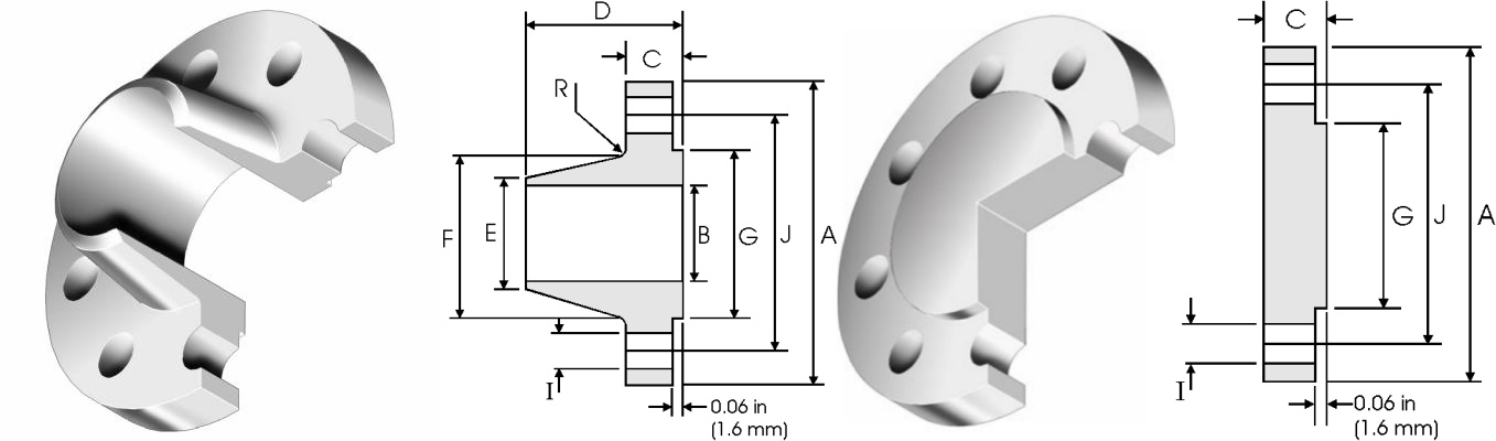
| Nominal Pipe Size | A | C | D | E | F | G | H | I | J | R | |
| mm | mm | mm | mm | mm | mm | mm | Holes | mm | mm | mm | |
| 22 | 749.3 | 45.97 | 45.97 | 149.35 | 558.8 | 609.6 | 641.35 | 20 | 35.05 | 692.15 | 9.65 |
| 26 | 869.95 | 68.33 | 68.33 | 120.65 | 660.4 | 676. 15 | 749.3 | 24 | 35.05 | 806.45 | 9.65 |
| 28 | 927.1 | 71.37 | 71.37 | 125.48 | 711.2 | 726.95 | 800.1 | 28 | 35.05 | 863.6 | 11.18 |
| 30 | 984.25 | 74.68 | 74.68 | 136.65 | 762 | 781.05 | 857.25 | 28 | 35.05 | 914.4 | 11.18 |
| 32 | 1060.5 | 81.03 | 81.03 | 144.53 | 812.8 | 831.85 | 914.4 | 28 | 41.15 | 977.9 | 11.18 |
| 34 | 1111.3 | 82.55 | 82.55 | 149.35 | 863.6 | 882.65 | 965.2 | 32 | 41.15 | 1028.7 | 12.70 |
| 36 | 1168.4 | 90.42 | 90.42 | 157.23 | 914.4 | 933.45 | 1022.4 | 32 | 41.15 | 1085.9 | 12.70 |
| 38 | 1238.3 | 87.38 | 87.38 | 157.23 | 965.2 | 990.60 | 1073.2 | 32 | 41.15 | 1149.4 | 12.70 |
| 40 | 1289.1 | 90.42 | 90.42 | 163.58 | 1016 | 1041.4 | 1124.0 | 36 | 41.15 | 1200.2 | 12.70 |
| 42 | 1346.2 | 96.77 | 96.77 | 171.45 | 1066.8 | 1092.2 | 1193.8 | 36 | 41.15 | 1257.3 | 12.70 |
| 44 | 1403.4 | 101.6 | 101.60 | 177.80 | 1117.6 | 1143 | 1244.6 | 40 | 41.15 | 1314.5 | 12.70 |
| 46 | 1454.2 | 103. 12 | 103.12 | 185.67 | 1168.4 | 1196.9 | 1295.4 | 40 | 41.15 | 1365.3 | 12.70 |
| 48 | 1511.3 | 107.95 | 107.95 | 192.02 | 1219.2 | 1247.7 | 1358.9 | 44 | 41.15 | 1422.4 | 12.70 |
| Nominal Pipe Size | A | C | D | E | F | G | H | I | J | R | |
| mm | mm | mm | mm | mm | mm | mm | Holes | mm | mm | mm | |
| 22 | 838.20 | 66.55 | 66.55 | 165.1 | 558.80 | 641.35 | 641.35 | 24 | 41.15 | 742.95 | 9.65 |
| 26 | 971.55 | 79.25 | 84.07 | 184.15 | 660.40 | 720.85 | 749.30 | 28 | 44.45 | 876.30 | 9.65 |
| 28 | 1035.1 | 85.85 | 90.42 | 196.85 | 711.20 | 774.70 | 800.10 | 28 | 44.45 | 939.80 | 11. 18 |
| 30 | 1092.2 | 91.95 | 95.25 | 209.55 | 762.00 | 827.02 | 857.25 | 28 | 47.75 | 996.95 | 11. 18 |
| 32 | 1149.4 | 98.55 | 100.08 | 222.25 | 812.80 | 881.13 | 914.40 | 28 | 50.80 | 1054. 1 | 11. 18 |
| 34 | 120.50 | 101.60 | 104.65 | 231.65 | 863.60 | 936.75 | 965.20 | 28 | 50.80 | 1104.9 | 12.70 |
| 36 | 1270.0 | 104.65 | 111.25 | 241.30 | 914.40 | 990.60 | 1022.40 | 32.00 | 53.85 | 1168.40 | 12.70 |
| 38 | 1168.4 | 107.95 | 107.95 | 180.85 | 965.20 | 993.65 | 1028.70 | 32.00 | 41.15 | 1092.20 | 12.70 |
| 40 | 1238.3 | 114.30 | 114.30 | 193.55 | 1016.00 | 1047.8 | 1085.90 | 32.00 | 44.45 | 1155.70 | 12.70 |
| 42 | 1289.1 | 119.13 | 119.13 | 200.15 | 1066.80 | 1098.6 | 1136.70 | 32.00 | 44.45 | 1206.60 | 12.70 |
| 44 | 1352.6 | 123.95 | 123.95 | 206.25 | 1117.60 | 1149.4 | 1193.80 | 32.00 | 47.75 | 1263.70 | 12.70 |
| 46 | 1416.1 | 128.52 | 128.52 | 215.90 | 1168.40 | 1203.5 | 1244.00 | 28.00 | 50.80 | 1320.80 | 12.70 |
| 48 | 1466.9 | 133.35 | 133.35 | 223.77 | 1219.20 | 1254.3 | 1301.80 | 32.00 | 50.80 | 1371.60 | 12.70 |
| Nominal Pipe Size | A | C | D | E | F | G | H | I | J | R | |
| mm | mm | mm | mm | mm | mm | mm | Holes | mm | mm | mm | |
| 26 | 762 | 33.27 | 33.27 | 58.67 | 661.92 | 676.15 | 704.85 | 36 | 19.05 | 723.9 | 7.87 |
| 28 | 812.8 | 33.27 | 33.27 | 61.98 | 712.72 | 726.95 | 755.65 | 40 | 19.05 | 774.70 | 7.87 |
| 30 | 863.6 | 33.27 | 33.27 | 65.02 | 763.52 | 777.75 | 806.45 | 44 | 19.05 | 825.50 | 7.87 |
| 32 | 914.4 | 35.05 | 36.58 | 69.85 | 814.32 | 828.55 | 857.25 | 48 | 19.05 | 876.30 | 7.87 |
| 34 | 965.2 | 35.05 | 38.10 | 73.15 | 865.12 | 879.35 | 908.05 | 52 | 19.05 | 927.10 | 7.87 |
| 36 | 1033.5 | 36.58 | 42.42 | 85.85 | 915.92 | 934.97 | 965.20 | 40 | 22.35 | 992.12 | 9.65 |
| 38 | 1084.3 | 38.10 | 44.45 | 88.90 | 966.72 | 985.77 | 1016.0 | 40 | 22.35 | 1042.9 | 9.65 |
| 40 | 1135.1 | 38.10 | 44.45 | 91.95 | 1017.5 | 1036.57 | 1066.8 | 44 | 22.35 | 1093.7 | 9.65 |
| 42 | 1185.9 | 39.62 | 47.75 | 95.25 | 1068.3 | 1087.37 | 1117.6 | 48 | 22.35 | 1144.5 | 9.65 |
| 44 | 1251.0 | 42.93 | 49.28 | 104.65 | 1119.1 | 1139.95 | 1174.8 | 36 | 25.40 | 1203.5 | 9.65 |
| 46 | 1301.8 | 44.45 | 50.80 | 107.95 | 1169.9 | 1190.75 | 1225.6 | 40 | 25.40 | 1254.3 | 9.65 |
| 48 | 1352.6 | 45.97 | 53.85 | 111.25 | 1220.7 | 1241.55 | 1276.4 | 44 | 25.40 | 1305. 1 | 9.65 |
| Nominal Pipe Size | A | C | D | E | F | G | H | I | J | R | |
| mm | mm | mm | mm | mm | mm | mm | Holes | mm | mm | mm | |
| 26 | 785.88 | 41.15 | 44.45 | 88.90 | 661.92 | 684.28 | 711.20 | 36 | 22.35 | 744.47 | 9.65 |
| 28 | 836.68 | 44.45 | 47.75 | 95.25 | 712.72 | 735.08 | 762.00 | 40 | 22.35 | 795.27 | 9.65 |
| 30 | 887.48 | 44.45 | 50.80 | 100.08 | 763.52 | 787.40 | 812.80 | 44 | 22.35 | 846.07 | 9.65 |
| 32 | 941.32 | 45.97 | 53.85 | 107.95 | 814.32 | 839.72 | 863.60 | 48 | 22.35 | 900.18 | 9.65 |
| 34 | 1004.8 | 49.28 | 57.15 | 110.24 | 865.12 | 892.05 | 920.75 | 40 | 25.40 | 957.33 | 9.65 |
| 36 | 1057.1 | 52.32 | 58.67 | 117.35 | 915.92 | 944.63 | 971.55 | 44 | 25.40 | 1009.7 | 9.65 |
| 38 | 1124.0 | 53.85 | 63.50 | 123.95 | 968.25 | 996.95 | 1022.4 | 40 | 28.45 | 1069.8 | 9.65 |
| 40 | 1174.8 | 55.63 | 66.55 | 128.52 | 1019.0 | 1049.3 | 1079.5 | 44 | 28.45 | 1120.6 | 9.65 |
| 42 | 1225.6 | 58.67 | 68.33 | 133.35 | 1069.8 | 1101.9 | 1130.3 | 48 | 28.45 | 1171.4 | 11.18 |
| 44 | 1276.4 | 60.45 | 71.37 | 136.65 | 1120.6 | 1152.7 | 1181.1 | 52 | 28.45 | 1222.2 | 11.18 |
| 46 | 1341.4 | 61.98 | 74.68 | 144.53 | 1171.4 | 1205.0 | 1234.9 | 40 | 31.75 | 1284.2 | 11.18 |
| 48 | 1392.2 | 65.02 | 77.72 | 149.35 | 1222.2 | 1257.3 | 1289.1 | 44 | 31.75 | 1335.0 | 11.18 |
The core distinction between ASME B16.47 Series A and B lies in their dimensional standards and applications. Series A (API 605-based) features larger bolt holes with fewer bolts and thicker necks for high-pressure oil and gas applications. Series B (MSS SP-44-based) has smaller but more numerous bolt holes with thinner necks, suitable for chemical and power industries. For example, NPS 36 Class 300 Series A has 24 bolts on a 1066.8mm circle, while Series B has 20 bolts on a 1041.4mm circle. Selection depends on specific pressure requirements and industry standards.
ASTM A105 is the most commonly used carbon steel material for ASME B16.47 welded neck flanges. Its chemical composition is mainly carbon (≤ 0.35%), manganese (0.60% -1.05%), and silicon (≤ 0.10%). It has excellent mechanical properties, with a tensile strength of 485-655MPa and a yield strength of ≥ 250MPa. It can be used for a long time in the temperature range of -29 ℃ to 427 ℃. This material flange has good welding and processing performance, and can be firmly connected to carbon steel pipelines through arc welding. It has low cost and is suitable for pipeline systems that transport neutral or weakly corrosive media such as water, steam, oil, and natural gas, such as urban heating pipelines, process pipelines of petroleum refining equipment, and water supply pipelines of thermal power plants.
Chemical Composition
| CHEMICAL | LIMITS | C | Mn | P | S | Si | Cu | Ni | Cr | Mo | V |
| ASTM A105 | MIN | 0.60 | 0.10 | ||||||||
| MAX | 0.35 | 1.05 | 0.035 | 0.040 | 0.35 | 0.40 | 0.40 | 0.30 | 0.12 | 0.08 |
Mechanical Properties
| MATERIAL | T.S (MPA) | Y.S (MPA) | EL % | R/A % | HARDNESS |
| ASTM A105 | 485 min | 250 min | 22 min | 30 min | 197 max |
In terms of manufacturing and inspection, ASTM A105 carbon steel flanges need to undergo forging forming (to ensure dense metal grains), normalizing treatment (to eliminate internal stress and improve toughness), surface shot blasting and rust removal (to reach Sa 2.5 level) and other processes; Finished product inspection should include size testing, appearance testing, magnetic particle testing (to detect surface cracks), and high-pressure specification flanges also need to undergo hydrostatic testing to ensure no leakage or structural defects.
The ASTM A182 standard covers ASME B16.47 welding neck flanges made of various stainless steel materials, among which F304 (18-8 stainless steel) and F316 (18-10-2 stainless steel) are the most widely used. F304 stainless steel flanges contain 18% -20% chromium and 8% -11% nickel, with excellent oxidation resistance and general corrosion resistance, suitable for medium and low pressure pipelines in the chemical, food and pharmaceutical industries; F316 stainless steel flanges have significantly improved resistance to pitting and inter granular corrosion due to the addition of 2% -3% molybdenum element. They can work stably in corrosive media environments containing chloride ions and sulfate ions, such as seawater treatment systems, acid and alkali solution pipelines, and cooling water pipelines in nuclear power plants.
Chemical Composition
| CHEMICAL | LIMITS | C | Mn | P | S | Si | Ni | Cr | Mo | N |
| ASTM A182 F304 | MIN | 8.0 | 18.0 | |||||||
| MAX | 0.08 | 2.00 | 0.045 | 0.030 | 1.00 | 11.0 | 20.0 | 0.10 | ||
| ASTM A182 F316 | MIN | 10.0 | 16.0 | 2.00 | ||||||
| MAX | 0.08 | 2.00 | 0.045 | 0.030 | 1.00 | 14.0 | 18.0 | 3.00 | 0.01 |
Mechanical Properties
| MATERIAL | T.S (MPA) | Y.S (MPA) | EL % | R/A % |
| ASTM A182 F304 | 515 min | 205 min | 30 min | 50 min |
| ASTM A182 F316 | 515 min | 205 min | 30 min | 50 min |
The manufacturing process of this material flange focuses on surface quality and corrosion resistance. After forming, it needs to undergo solution treatment (water quenching at 1010 ℃ -1150 ℃ to restore the corrosion resistance of stainless steel), and the sealing surface roughness should reach Ra ≤ 3.2 μ m; In terms of inspection, in addition to routine size and appearance testing, inter granular corrosion testing and penetration testing are also required to ensure that cracking or leakage will not occur under high temperature and corrosive conditions.
ASME B16.47 welding neck flanges are widely used in multiple major industrial fields due to their advantages of large diameter and high pressure resistance
Oil and gas industry
Chemical industry
Power industry
Municipal engineering
In addition, ASME B16.47 welded neck flanges play an irreplaceable role in the metallurgical industry (oxygen pipelines for steel making converters), shipbuilding (ballast water pipelines for large ships), and hydraulic engineering (water pipelines for large pumping stations), providing core support for the safe operation of large industrial systems.
As the core component of large-diameter pipeline connections, ASME B16.47 welding neck flanges have strict standard specifications, diverse material selection, and strict size control, which enable them to adapt to harsh working conditions in different industries.
