

Views: 37 Author: Site Editor Publish Time: 2025-11-18 Origin: Site


ASME B16.9 carbon steel butt welded pipe fittings have multiple advantages and play important roles in connecting, turning, and reducing in industrial pipeline systems.
Butt weld fittings are an important type of pipe fittings in industrial pipeline systems, which are connected to pipelines through welding to achieve functions such as turning, reducing, branching, and end sealing of pipelines.
During the welding process of welded pipe fittings, it is necessary to perform bevel treatment on the ends of the fittings and pipes, and then use welding technology to connect them to the pipes. This connection method can not only effectively avoid medium leakage, but also reduce pressure loss in the pipeline system and improve the operating efficiency of the pipeline system.
The ASME B16.9 standard (Download) is a standard specification developed by the American Society of Mechanical Engineers (ASME) for forged steel butt welded pipe fittings manufactured in factories. This standard has been widely recognized and applied worldwide, providing a unified technical basis for the design, manufacturing, inspection, and acceptance of butt welded pipe fittings.
| Material | ASTM A234 WPB |
| Standard | ASME/ANSI B16.9, ASME B16.28, ASME B16.49,MSS-SP-43 |
| Size | 1/8"- 48″(DN6-DN1200) |
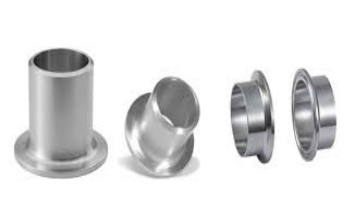
| Types | Butt Weld Elbow、Tee、Cross、Reducer、Cap、Stub End |
| Thickness | Sch 5s, Sch 10s, Sch 40s, Sch 80s, Sch 160s, Sch XXS |
The ASME B16.9 standard applies to butt welded fittings with nominal sizes ranging from 1/2 inch (DN15) to 48 inches (DN1200), covering various common pipe specifications. At the same time, this standard is applicable to welded fittings made of various materials such as carbon steel, alloy steel, and stainless steel, which can meet the needs of different industrial environments.
According to ASME B16.9 standard, butt welded pipe fittings mainly include various product types such as butt welded elbows, butt welded tees, butt welded tees, reducers, butt welded pipe caps, and flanged short sections. These different types of butt welded pipe fittings each have unique structures and functions, which can meet different installation requirements in pipeline systems.
The ASME B16.9 standard provides strict specifications for the manufacturing process, dimensional tolerances, material properties, inspection methods, and marking requirements of forged steel butt welded pipe fittings.
Overall dimensions: Key dimensions for various types of fittings are specified, such as end outer diameter, center to end distance, wall thickness, etc.
Tolerance: specifies the manufacturing deviation allowed for the above dimensions.
Pressure rating: defines the working pressure of the pipe fittings at different temperatures and materials.
Testing: may include inspection and testing requirements for materials or finished pipe fittings, such as non-destructive testing, pressure testing, etc.
Marking: specifies the information that must be marked on the pipe fittings, such as standard number, material grade, size, pressure rating, etc., for easy identification and traceability.
ASME B16.9 offers a wide variety of carbon steel butt weld fittings, each with specific size specifications to meet the installation needs of different piping systems.

Butt weld elbow is the most widely used type of carbon steel butt welded pipe fittings in ASME B16.9, mainly used to achieve pipeline turning.
According to the different bending angles of elbows, they can be divided into three common types: 45 ° elbows, 90 ° elbows, and 180 ° elbows;
According to different bending radii, it can be divided into long radius elbows (1.5D LR) and short radius elbows (1D SR);
In terms of size, the nominal size range of butt welded elbows is from 1/2 inch (DN15) to 48 inches (DN1200), and their outer diameter and wall thickness are designed and manufactured according to the corresponding pipeline standards (such as ANSI B36.10).
Dimension of 90 Deg and 45 Deg Elbow

| BW 90 LR/SR Elbow | BW 45 LR Elbow | ||||
| ASME B16.9 | |||||
| Nominal Size | Outside Diameter at Bevel | Center to End | |||
| 90° Elbows | 45° Elbows | ||||
| DN | NPS | OD | A | B | |
| LR | SR | LR | |||
| 15 | 1/2 | 21.3 | 38 | 16 | |
| 20 | 3/4 | 26.7 | 38 | 19 | |
| 25 | 1 | 33.4 | 38 | 25 | 22 |
| 32 | 1 1/4 | 42.2 | 48 | 32 | 25 |
| 40 | 1 1/2 | 48.3 | 57 | 38 | 29 |
| 50 | 2 | 60.3 | 76 | 51 | 35 |
| 65 | 2 1/2 | 73.0 | 95 | 64 | 44 |
| 80 | 3 | 88.9 | 114 | 76 | 51 |
| 90 | 3 1/2 | 101.6 | 133 | 89 | 57 |
| 100 | 4 | 114.3 | 152 | 102 | 64 |
| 125 | 5 | 141.3 | 190 | 127 | 79 |
| 150 | 6 | 168.3 | 229 | 152 | 95 |
| 200 | 8 | 219.1 | 305 | 203 | 127 |
| 250 | 10 | 273.0 | 381 | 254 | 159 |
| 300 | 12 | 323.8 | 457 | 305 | 190 |
| 350 | 14 | 355.6 | 533 | 356 | 222 |
| 400 | 16 | 406.4 | 610 | 406 | 254 |
| 450 | 18 | 457.0 | 686 | 457 | 286 |
| 500 | 20 | 508.0 | 762 | 508 | 318 |
| 550 | 22 | 559.0 | 838 | 559 | 343 |
| 600 | 24 | 610.0 | 914 | 610 | 381 |
| 650 | 26 | 660.0 | 991 | 660 | 406 |
| 700 | 28 | 711.0 | 1067 | 711 | 438 |
| 750 | 30 | 762.0 | 1143 | 762 | 470 |
| 800 | 32 | 813.0 | 1219 | 813 | 502 |
| 850 | 34 | 864.0 | 1295 | 864 | 533 |
| 900 | 36 | 914.0 | 1372 | 914 | 565 |
| 950 | 38 | 965.0 | 1448 | 965 | 600 |
| 1000 | 40 | 1016.0 | 1524 | 1016 | 632 |
| 1050 | 42 | 1067.0 | 1600 | 1067 | 660 |
| 1100 | 44 | 1118.0 | 1676 | 1118 | 695 |
| 1150 | 46 | 1168.0 | 1753 | 1168 | 727 |
| 1200 | 48 | 1219.0 | 1829 | 1219 | 759 |
Dimension of 3D and 180 Deg Elbow


| BW 90 3D Elbow | BW 45 3D Elbow | BW 180 LR/SR Return | ||||||
| ASME B16.9 | ||||||||
| Nominal Size | Outside Diameter at Bevel | Center to End | Center to Center | Back to Face | ||||
| 90° Elbows | 45° Elbows | 180 Returns | ||||||
| DN | NPS | OD | A | B | O | K | ||
| 3D | 3D | LR | SR | LR | SR | |||
| 15 | 1/2 | 21.3 | 76 | 48 | ||||
| 20 | 3/4 | 26.7 | 57 | 24 | 76 | 51 | ||
| 25 | 1 | 33.4 | 76 | 31 | 76 | 51 | 56 | 41 |
| 32 | 1 1/4 | 42.2 | 95 | 39 | 95 | 64 | 70 | 52 |
| 40 | 1 1/2 | 48.3 | 114 | 47 | 114 | 76 | 83 | 62 |
| 50 | 2 | 60.3 | 152 | 63 | 152 | 102 | 106 | 81 |
| 65 | 2 1/2 | 73.0 | 190 | 79 | 190 | 127 | 132 | 100 |
| 80 | 3 | 88.9 | 229 | 95 | 229 | 152 | 159 | 121 |
| 90 | 3 1/2 | 101.6 | 267 | 111 | 267 | 178 | 184 | 140 |
| 100 | 4 | 114.3 | 305 | 127 | 305 | 203 | 210 | 159 |
| 125 | 5 | 141.3 | 381 | 157 | 381 | 254 | 262 | 197 |
| 150 | 6 | 168.3 | 457 | 189 | 457 | 305 | 313 | 237 |
| 200 | 8 | 219.1 | 610 | 252 | 610 | 406 | 414 | 313 |
| 250 | 10 | 273.0 | 762 | 316 | 508 | 518 | 391 | |
| 300 | 12 | 323.8 | 914 | 378 | 914 | 609 | 619 | 467 |
| 350 | 14 | 355.6 | 1067 | 441 | 1067 | 711 | 711 | 533 |
| 400 | 16 | 406.4 | 1219 | 505 | 1219 | 813 | 813 | 610 |
| 450 | 18 | 457.0 | 1372 | 568 | 1372 | 914 | 914 | 686 |
| 500 | 20 | 508.0 | 1524 | 632 | 1524 | 1016 | 1016 | 762 |
| 550 | 22 | 559.0 | 1676 | 694 | 1676 | 1118 | 1118 | 838 |
| 600 | 24 | 610.0 | 1829 | 757 | 1829 | 1219 | 1219 | 914 |
| 650 | 26 | 660.0 | 1981 | 821 | ||||
| 700 | 28 | 711.0 | 2134 | 883 | ||||
| 750 | 30 | 762.0 | 2286 | 964 | ||||
| 800 | 32 | 813.0 | 2438 | 1010 | ||||
| 850 | 34 | 864.0 | 2591 | 1073 | ||||
| 900 | 36 | 914.0 | 2743 | 1135 | ||||
| 950 | 38 | 965.0 | 2896 | 1200 | ||||
| 1000 | 40 | 1016.0 | 3048 | 1264 | ||||
| 1050 | 42 | 1067.0 | 3200 | 1326 | ||||
| 1100 | 44 | 1118.0 | 3353 | 1389 | ||||
| 1150 | 46 | 1168.0 | 3505 | 1453 | ||||
| 1200 | 48 | 1219.0 | 3658 | 1516 | ||||

ASME B16.9 carbon steel butt welded tees are used to branch pipelines, allowing the pipeline system to transport media from the main pipeline to the branch pipeline. According to the different structural forms of tees, they can be divided into two types: equal diameter tees and reducing diameter tees.
The nominal size of the three ports of the equal diameter tee is the same, while the nominal size of the main port of the different diameter tee is larger than that of the branch port.
The nominal size range for butt welded tees is also from 1/2 inch (DN15) to 48 inches (DN1200), and the outer diameter and wall thickness of the main and branch pipes also follow the corresponding pipeline standards.
ASME B16.9 Dimensional for Butt Welded Tee

Nominal Size | Outside Diameter at Bevel | Center to End | ||
DN | NPS | OD | C | M |
15 | 1/2 | 21.3 | 25 | 25 |
20 | 3/4 | 26.7 | 29 | 29 |
25 | 1 | 33.4 | 38 | 38 |
32 | 1.1/4 | 42.2 | 48 | 48 |
40 | 1.1/2 | 48.3 | 57 | 57 |
50 | 2 | 60.3 | 64 | 64 |
65 | 2.1/2 | 73.0 | 76 | 76 |
80 | 3 | 88.9 | 86 | 86 |
90 | 3.1/2 | 101.6 | 95 | 95 |
100 | 4 | 114.3 | 105 | 105 |
125 | 5 | 141.3 | 124 | 124 |
150 | 6 | 168.3 | 143 | 143 |
200 | 8 | 219.1 | 178 | 178 |
250 | 10 | 273.0 | 216 | 216 |
300 | 12 | 323.8 | 254 | 254 |
350 | 14 | 355.6 | 279 | 279 |
400 | 16 | 406.4 | 305 | 305 |
450 | 18 | 457.0 | 343 | 343 |
500 | 20 | 508.0 | 381 | 381 |
550 | 22 | 559.0 | 419 | 419 |
600 | 24 | 610.0 | 432 | 432 |
650 | 26 | 660.0 | 495 | 495 |
700 | 28 | 711.0 | 521 | 521 |
750 | 30 | 762.0 | 559 | 559 |
800 | 32 | 813.0 | 597 | 597 |
850 | 34 | 864.0 | 635 | 635 |
900 | 36 | 914.0 | 673 | 673 |
950 | 38 | 965.0 | 711 | 711 |
1000 | 40 | 1016.0 | 749 | 749 |
1050 | 42 | 1067.0 | 762 | 762 |
1100 | 44 | 1118.0 | 813 | 813 |
1150 | 46 | 1168.0 | 851 | 851 |
1200 | 48 | 1219.0 | 889 | 889 |
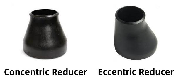
Butt welded reducers, also known as reducing pipes, are used to connect pipes of different diameters. They are divided into two types: concentric reducers (CONC) and eccentric reducers (ECC).
The centers of the two ends of the concentric head are on the same straight line, suitable for general pipeline variable diameter connections;
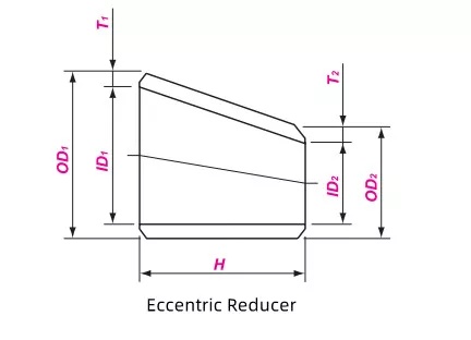
The centers of the two ends of the eccentric head are not on the same straight line, mainly used to prevent the accumulation of medium in the pipeline. It is commonly used in pump inlets, horizontal pipelines, and pipeline systems that require drainage.
The nominal size range of ASME B16.9 carbon steel concentric and eccentric reducers is from 1/2 inch (DN15) to 48 inches (DN1200), and the outer diameter and wall thickness of the large and small ends are designed according to the corresponding pipeline standards.
The size parameters of eccentric reducers are similar to those of concentric reducers, except for the difference in eccentricity in structure. The eccentricity is determined based on the nominal size and pipeline standards to ensure the smoothness of pipeline connections and the normal flow of media.
Dimensional of BW Reducer
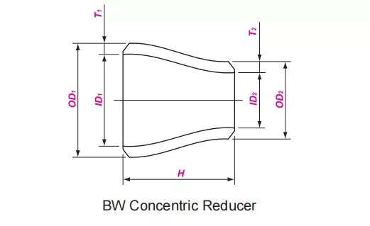
Nominal Size | Outside Diameter at Bevel | Center to End | ||||
DN1 | DN2 | NPS1 | NPS2 | OD1 | OD2 | H |
20 | 10-15 | 3/4 | 3/8-1/2 | 26.7 | 17.1-21.3 | 38 |
25 | 15-20 | 1 | 1/2-3/4 | 33.4 | 21.3-26.7 | 51 |
32 | 15-25 | 1 1/4 | 1/2-1 | 42.2 | 21.3-33.4 | 51 |
40 | 15-32 | 1 1/2 | 1/2-1 1/4 | 48.3 | 21.3-42.2 | 64 |
50 | 20-40 | 2 | 3/4-1 1/2 | 60.3 | 26.7-48.3 | 76 |
65 | 25-50 | 2 1/2 | 1-2 | 73.0 | 33.4-60.3 | 89 |
80 | 32-65 | 3 | 1 1/4-2 1/2 | 88.9 | 42.2-73.0 | 89 |
90 | 32-80 | 3 1/2 | 1 1/4-3 | 101.6 | 42.2-88.9 | 102 |
100 | 40-90 | 4 | 1 1/2-3 1/2 | 114.3 | 48.3-101.6 | 102 |
125 | 50-100 | 5 | 2-4 | 141.3 | 60.3-114.3 | 127 |
150 | 65-125 | 6 | 2 1/2-5 | 168.3 | 73.0-141.3 | 140 |
200 | 90-150 | 8 | 3 1/2-6 | 219.1 | 101.6-168.3 | 152 |
250 | 100-200 | 10 | 4-8 | 273.0 | 114.3-219.1 | 178 |
300 | 125-250 | 12 | 5-10 | 323.8 | 141.3-273.0 | 203 |
350 | 150-300 | 14 | 6-12 | 355.6 | 168.3-323.8 | 330 |
400 | 150-350 | 16 | 6-14 | 406.4 | 168.3-355.6 | 356 |
450 | 200-400 | 18 | 8-16 | 457.0 | 219.1-406.4 | 381 |
500 | 250-450 | 20 | 10-18 | 508.0 | 273.0-457.0 | 508 |
550 | 300-500 | 22 | 12-20 | 559.0 | 323.8-508.0 | 508 |
600 | 300-550 | 24 | 12-22 | 610.0 | 323.8-559.0 | 508 |
650 | 350-600 | 26 | 14-24 | 660 | 355.6-610.0 | 610 |
700 | 350-650 | 28 | 14-26 | 711 | 355.6-660.0 | 610 |
750 | 350-700 | 30 | 14-28 | 762 | 355.6-711.0 | 610 |
800 | 500-750 | 32 | 20-30 | 813 | 508.0-762.0 | 610 |
850 | 550-800 | 34 | 22-32 | 864 | 559.0-813.0 | 610 |
900 | 550-850 | 36 | 22-34 | 914 | 559.0-864.0 | 610 |
950 | 600-900 | 38 | 24-36 | 965 | 610.0-914.0 | 610 |
1000 | 700-950 | 40 | 28-38 | 1016 | 711.0-965.0 | 610 |
1050 | 700-1000 | 42 | 28-40 | 1067 | 711.0-1016.0 | 610 |
1100 | 800-1050 | 44 | 32-42 | 1118 | 813.0-1067.0 | 610 |
1150 | 850-1100 | 46 | 34-44 | 1168 | 864.0-1118.0 | 711 |
1200 | 900-1150 | 48 | 36-46 | 1219 | 914.0-1168.0 | 711 |
1300 | 1000-1200 | 52 | 40-48 | 1321 | 1016.0-1219.0 | 711 |
1400 | 1100-1300 | 56 | 40-52 | 1422 | 1016.0-1321.0 | 711 |
1500 | 1100-1400 | 60 | 44-56 | 1524 | 1118.0-1422.0 | 711 |
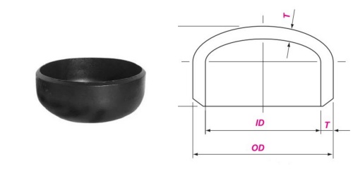
The butt welded pipe cap is used to seal the end of the pipeline, preventing medium leakage and external impurities from entering the pipeline, and protecting the safe operation of the pipeline system. The nominal size range of ASME B16.9 carbon steel butt welded pipe cap is from 1/2 inch (DN15) to 48 inches (DN1200), and its outer diameter and wall thickness are consistent with the corresponding nominal size of the pipeline to ensure good connection with the pipeline.
ASME B16.9 Dimensions of Buttwelding Pipe Cap
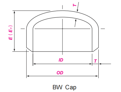
DN | NPS | OD | E | E1 |
15 | 1/2 | 21.3 | 25 | 25 |
20 | 3/4 | 26.7 | 25 | 25 |
25 | 1 | 33.4 | 38 | 38 |
32 | 11/4 | 42.2 | 38 | 38 |
40 | 11/2 | 48.3 | 38 | 38 |
50 | 2 | 60.3 | 38 | 44 |
65 | 21/2 | 73.0 | 38 | 51 |
80 | 3 | 88.9 | 51 | 64 |
90 | 31/2 | 101.6 | 64 | 76 |
100 | 4 | 114.3 | 64 | 76 |
125 | 5 | 141.3 | 76 | 89 |
150 | 6 | 168.3 | 89 | 102 |
200 | 8 | 219.1 | 102 | 127 |
250 | 10 | 273.0 | 127 | 152 |
300 | 12 | 323.8 | 152 | 178 |
350 | 14 | 355.6 | 165 | 191 |
400 | 16 | 406.4 | 178 | 203 |
450 | 18 | 457.0 | 203 | 229 |
500 | 20 | 508.0 | 229 | 254 |
550 | 22 | 559.0 | 254 | 254 |
600 | 24 | 610.0 | 267 | 305 |
650 | 26 | 660.0 | 267 | --- |
700 | 28 | 711.0 | 267 | --- |
750 | 30 | 762.0 | 267 | --- |
800 | 32 | 813.0 | 267 | --- |
850 | 34 | 864.0 | 267 | --- |
900 | 36 | 914.0 | 267 | --- |
950 | 38 | 965.0 | 305 | --- |
1000 | 40 | 1016.0 | 305 | --- |
1050 | 42 | 1067.0 | 305 | --- |
1100 | 44 | 1118.0 | 343 | --- |
1150 | 46 | 1168.0 | 343 | --- |
1200 | 48 | 1219.0 | 343 | --- |
Stub End is a short pipe with a flanged structure, mainly used in conjunction with flanges to enhance the strength and sealing of the connection between pipes and flanges, while also facilitating the installation and disassembly of pipes. The nominal size range of ASME B16.9 carbon steel flanged short sections is from 1/2 inch (DN15) to 24 inches (DN600), with the same outer diameter and wall thickness as the corresponding pipeline specifications. The height and thickness of the flange are determined according to the flange standards and sealing requirements.
ASTM A234 Dimensions of Stub End
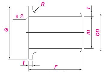
Nominal Size | OD of Cylinder | Length | Radius of Fillet | Diameter | ||||
DN | NPS | OD | F | R | ||||
Max. | Min. | 长型 | 短型 | A | B max | G | ||
15 | 1/2 | 22.8 | 20.5 | 76 | 51 | 3 | 0.8 | 35 |
20 | 3/4 | 28.1 | 25.9 | 76 | 51 | 3 | 0.8 | 43 |
25 | 1 | 35.0 | 32.6 | 102 | 51 | 3 | 0.8 | 51 |
32 | 1 1/4 | 43.6 | 41.4 | 102 | 51 | 5 | 0.8 | 64 |
40 | 1 1/2 | 49.9 | 47.5 | 102 | 51 | 6 | 0.8 | 73 |
50 | 2 | 62.4 | 59.5 | 152 | 64 | 8 | 0.8 | 92 |
65 | 2 1/2 | 75.3 | 72.2 | 152 | 64 | 8 | 0.8 | 105 |
80 | 3 | 91.3 | 88.1 | 152 | 64 | 10 | 0.8 | 127 |
90 | 3 1/2 | 104.0 | 100.8 | 152 | 76 | 10 | 0.8 | 140 |
100 | 4 | 116.7 | 113.5 | 152 | 76 | 11 | 0.8 | 157 |
125 | 5 | 144.3 | 140.5 | 203 | 76 | 11 | 1.6 | 186 |
150 | 6 | 171.3 | 167.5 | 203 | 89 | 13 | 1.6 | 216 |
200 | 8 | 222.1 | 218.3 | 203 | 102 | 13 | 1.6 | 270 |
250 | 10 | 277.2 | 272.3 | 254 | 127 | 13 | 1.6 | 324 |
300 | 12 | 328.0 | 323.1 | 254 | 152 | 13 | 1.6 | 381 |
350 | 14 | 359.9 | 354.8 | 305 | 152 | 13 | 1.6 | 413 |
400 | 16 | 411.0 | 405.6 | 305 | 152 | 13 | 1.6 | 470 |
450 | 18 | 462.0 | 456.0 | 305 | 152 | 13 | 1.6 | 533 |
500 | 20 | 514.0 | 507.0 | 305 | 152 | 13 | 1.6 | 584 |
550 | 22 | 565.0 | 558.0 | 305 | 152 | 13 | 1.6 | 641 |
600 | 24 | 616.0 | 609.0 | 305 | 152 | 13 | 1.6 | 692 |
Nominal Size | All Fittings | 45°&90° Elbows |
| 180° Returns | Caps | Reducers & Lap Joint | Lap Joint Stub Ends | ||||||
DN | NPS | OD 3) 4) | ID 3) | A B C M | A B |
| K | U | E, E1 | H F |
| R | t |
15-65 | 1/2 -21/2 | +1.6 | ± 0.8 | ± 2 | ± 3 | ± 6 | ± 6 | ± 1 | ± 3 | ± 2 | 0 | 0 | +1.6 |
80-90 | 3-31/2 | ± 1.6 | ± 1.6 | ± 2 | ± 3 | ± 6 | ± 6 | ± 1 | ± 3 | ± 2 | 0 | 0 | +1.6 |
100 | 4 | ± 1.6 | ± 1.6 | ± 2 | ± 3 | ± 6 | ± 6 | ± 1 | ± 3 | ± 2 | 0 | 0 | +1.6 |
125-200 | 5-8 | +2.4 | ± 1.6 | ± 2 | ± 3 | ± 6 | ± 6 | ± 1 | ± 6 | ± 2 | 0 | 0 | +1.6 |
250-450 | 10-18 | +4.0 | ± 3.2 | ± 2 | ± 3 | ± 10 | ± 6 | ± 2 | ± 6 | ± 2 | 0 | 0 | +3.2 |
500-600 | 20-24 | +6.4 | ± 4.8 | ± 2 | ± 3 | ± 10 | ± 6 | ± 2 | ± 6 | ± 2 | 0 | 0 | +3.2 |
650-750 | 26-30 | +6.4 | ± 4.8 | ± 3 | ± 6 | --- | --- | --- | ± 10 | ± 5 | --- | --- | --- |
800-1200 | 32-48 | +6.4 | ± 4.8 | ± 5 | ± 6 | --- | --- | --- | ± 10 | ± 5 | --- | --- | --- |
1300-1500 | 52-60 | +6.4 | ± 4.8 | ± 5 | --- | --- | --- | --- | --- | --- | --- | --- | --- |
1600-1700 | 64-68 | +6.4 | ± 4.8 | ± 5 | --- | --- | --- | --- | --- | --- | --- | --- | --- |
1800-2000 | 72-80 | +6.4 | ± 4.8 | ± 5 | --- | --- | --- | --- | --- | --- | --- | --- | --- |
In ASME B16.9 carbon steel butt welded pipe fittings, ASTM A234 WPB material butt welded pipe fittings have been widely used in many industrial fields due to their excellent comprehensive performance.
ASTM A234 is a standard specification for forged carbon steel and alloy steel pipe fittings for medium temperature use developed by the American Society for Testing and Materials (ASTM), while WPB is a specific carbon steel material grade specified in the standard.
W "represents welding, indicating that the material of the pipe fittings is suitable for welding connections;
P "represents Pipe, indicating that this material is mainly used for the manufacturing of pipe fittings in pipeline systems;
B "is the grade designation of the material in ASTM A234 standard, representing specific chemical composition and mechanical performance requirements.
ASTM A234 WPB material butt welded fittings have excellent mechanical and welding properties, high temperature and high pressure resistance, ensuring the structural stability of the pipeline system during operation.
Chemical composition
| CHEMICAL | LIMITS | C | Mn | P | S | Si | Cr | Mo | Ni | Cu | Cb | V |
| ASTM A234 WPB | MIN | 0.29 | 0.10 | |||||||||
| MAX | 0.30 | 1.06 | 0.050 | 0.058 | 0.40 | 0.15 | 0.40 | 0.40 | / | 0.08 |
Mechanical properties
| MATERIAL | T.S (MPA) | Y.S (MPA) | EL % | HARDNESS |
| ASTM A234 WPB | 415 min | 240 min | 22 min | 197 max |
In industrial pipeline systems, butt welded pipe fittings and socket welded pipe fittings are two commonly used types of pipe fittings, which have significant differences in structure, connection methods, performance characteristics, and applicable scenarios, and each has its own advantages and disadvantages.
The end of the welded pipe fittings adopts a groove form, which forms a continuous weld connection with the pipeline through welding, and the strength of the welded joint is relatively high;
Socket welded pipe fittings have a socket, and after the pipe is inserted into the socket, it is welded at the gap between the socket and the pipe to form a fillet weld connection.
Advantages of BW Fittings
Good sealing performance: The welding joint between the welded pipe fittings and the pipeline is a continuous weld seam, which can effectively prevent medium leakage.
Excellent mechanical performance: The strength of welded joints can withstand high pressure, temperature, and vibration loads, improving overall stability and safety.
Wide applicability: Welded pipe fittings are suitable for pipeline systems in high-pressure and high-temperature environments, with nominal sizes ranging from 1/2 inch to 48 inches, and can meet the needs of different industrial fields.
Advantages of SW Fittings
Easy installation: The installation process of socket welding fittings is relatively simple, and the pipeline only needs to be inserted into the socket and welded, resulting in high installation efficiency.
Easy maintenance: In some small pipeline systems, if replacement of fittings is required, the disassembly and replacement of socket welding fittings are relatively easy, which can reduce maintenance workload and costs.
Butt Wedl Fittings
Difficulty in installation
High requirements for installation environment
Socket Weld Fittings
Poor sealing performance
Limited mechanical properties
High flow resistance
narrow scope of application
ASTM A234 and ASTM A403 are both material standards for forged pipe fittings developed by the American Society for Testing and Materials. There are certain differences between the two in terms of application scope, material type, performance requirements, etc., and they are suitable for different industrial scenarios.
The ASTM A234 standard is applicable to carbon steel and alloy steel butt welded pipeline fittings, mainly used in pipeline systems at room temperature, covering various types such as butt welded elbows, tees, tees, pipe caps, reducers, and flanged short joints;
The ASTM A403 standard is applicable to austenitic stainless steel butt welded fittings, mainly used in pipeline systems with high corrosion resistance requirements. It also covers various types of butt welded fittings such as butt welded elbows, tees, crosses, pipe caps, reducers, and flanged short joints.
The ASTM A234 standard mainly includes carbon steel and alloy steel materials. Common grades of carbon steel materials include WPB, WPC, etc., while alloy steel grades include WP1, WP5, WP9, WP11, WP22, WP91, etc. Different grades of materials have different chemical compositions and mechanical properties to meet the needs of use under different temperature and pressure conditions;
The ASTM A403 standard mainly includes austenitic stainless steel materials, with common grades including WP304, WP304L, WP316, WP316L, WP321, WP347, etc. These materials have excellent corrosion resistance, can resist the erosion of various corrosive media, and also have good high-temperature strength and oxidation resistance.
ASME B16.9 carbon steel butt welded pipe fittings play an indispensable role in multiple industrial fields due to their strict quality standards, diverse product types, and adaptability to different working conditions. The specific application scope is as follows:
Petrochemical industry
Natural gas transportation industry
power industry
Metallurgical industry
Municipal Engineering and Other Fields
ASME B16.9 carbon steel butt welded pipe fittings have become key components in industrial pipeline systems due to their strict standard specifications, comprehensive product types, excellent performance, and wide applicability, providing solid guarantees for production safety and efficient operation in various industries.
