

Views: 1 Author: Site Editor Publish Time: 2026-03-06 Origin: Site


Blind flange is a solid steel flange without a center hole. Its key feature is that it has no opening in the middle – it's a solid round plate with bolt holes around the edge. Sealing face types include RF, FF, RTJ, etc.
Pipe sealing – closes the end of a pipe to stop media flow;
Equipment protection – installed at equipment inlets/outlets to prevent debris entry;
Pressure testing – used as a temporary seal during pipe pressure and leak testing, bearing the full test pressure.
Notably, because it withstands full cross-sectional pressure, the blind flange is often the thickest type among flanges of the same size.
ASME stands for the American Society of Mechanical Engineers. Founded in 1880, it works to advance science and technology in mechanical engineering and related fields, and carries out standardization activities.
The core of its standard system is the world-renowned Boiler and Pressure Vessel Code (BPVC), which provides unified and safe rules for the design, manufacturing, and inspection of pressure equipment. Additionally, ASME has developed over 600 standards and codes covering areas like performance testing and piping systems.
These standards, known for their authority and rigor, have been adopted by over 100 countries worldwide. They are a cornerstone for ensuring public safety, promoting international trade, and fostering technological innovation.
ASME standards related to blind flanges mainly include two systems: ASME B16.5 and ASME B16.47.
ASME B16.5: This is the most common standard for pipe flanges and flanged fittings, covering pressure classes Class 150 to Class 2500 and size range NPS 1/2 to NPS 24.

NPS | A | C | G | H | I | J | W |
inch | inch | inch | No. of holes | inch | inch | kg/pc | |
mm | mm | mm | mm | mm | |||
1/2 | 3.500 | 0.440 | 1.380 | 4 | 0.620 | 2.380 | 0.42 |
88.90 | 11.20 | 35.10 | 15.70 | 60.45 | |||
3/4 | 3.880 | 0.500 | 1.690 | 4 | 0.620 | 2.750 | 0.61 |
98.60 | 12.70 | 42.90 | 15.70 | 69.85 | |||
1 | 4.250 | 0.560 | 2.000 | 4 | 0.620 | 3.120 | 0.86 |
108.0 | 14.20 | 50.80 | 15.70 | 79.25 | |||
1-1/4 | 4.620 | 0.620 | 2.500 | 4 | 0.620 | 3.500 | 1.17 |
117.3 | 15.70 | 63.50 | 15.70 | 88.90 | |||
1-1/2 | 5.000 | 0.690 | 2.880 | 4 | 0.620 | 3.880 | 1.53 |
127.0 | 17.50 | 73.15 | 15.70 | 98.60 | |||
2 | 6.000 | 0.750 | 3.620 | 4 | 0.750 | 4.750 | 2.42 |
152.4 | 19.10 | 91.90 | 19.10 | 120.7 | |||
2-1/2 | 7.000 | 0.880 | 4.120 | 4 | 0.750 | 5.500 | 3.94 |
177.8 | 22.40 | 104.6 | 19.10 | 139.7 | |||
3 | 7.500 | 0.940 | 5.000 | 4 | 0.750 | 6.000 | 4.93 |
190.5 | 23.90 | 127.0 | 19.10 | 152.4 | |||
3-1/2 | 8.500 | 0.940 | 5.500 | 8 | 0.750 | 7.000 | 6.17 |
215.9 | 23.90 | 139.7 | 19.10 | 177.8 | |||
4 | 9.000 | 0.940 | 6.190 | 8 | 0.750 | 7.500 | 7.00 |
228.6 | 23.90 | 157.2 | 19.10 | 190.5 | |||
5 | 10.00 | 0.940 | 7.310 | 8 | 0.880 | 8.500 | 8.63 |
254.0 | 23.90 | 185.7 | 22.40 | 215.9 | |||
6 | 11.00 | 1.000 | 8.500 | 8 | 0.880 | 9.500 | 11.3 |
279.4 | 25.40 | 215.9 | 22.40 | 241.3 | |||
8 | 13.50 | 1.120 | 10.62 | 8 | 0.880 | 11.75 | 19.6 |
342.9 | 28.40 | 269.7 | 22.40 | 298.5 | |||
10 | 16.00 | 1.190 | 12.75 | 12 | 1.000 | 14.25 | 28.8 |
406.4 | 30.20 | 323.9 | 25.40 | 362.0 | |||
12 | 19.00 | 1.250 | 15.00 | 12 | 1.000 | 17.00 | 43.2 |
482.6 | 31.75 | 381.0 | 25.40 | 431.8 | |||
14 | 21.00 | 1.380 | 16.25 | 12 | 1.120 | 18.75 | 58.1 |
533.4 | 35.10 | 412.8 | 28.40 | 476.3 | |||
16 | 23.50 | 1.440 | 18.50 | 16 | 1.120 | 21.25 | 76.0 |
596.9 | 36.60 | 469.9 | 28.40 | 539.8 | |||
18 | 25.00 | 1.560 | 21.00 | 16 | 1.250 | 22.75 | 93.7 |
635.0 | 39.60 | 533.4 | 31.75 | 577.9 | |||
20 | 27.50 | 1.690 | 23.00 | 20 | 1.250 | 25.00 | 122 |
698.5 | 42.90 | 584.2 | 31.75 | 635.0 | |||
24 | 32.00 | 1.880 | 27.25 | 20 | 1.380 | 29.50 | 185 |
812.8 | 47.80 | 692.2 | 35.10 | 749.3 |
ASME B16.47 Series A and Series B: This standard covers large diameter flanges (NPS 26 to NPS 60). Series A originates from MSS SP-44, suitable for general piping systems. Series B originates from API 605, suitable for the refinery and petrochemical industry.

| Nominal Pipe Size | A | C | D | E | F | G | H | I | J | R | |
| mm | mm | mm | mm | mm | mm | mm | Holes | mm | mm | mm | |
| 22 | 749.3 | 45.97 | 45.97 | 149.35 | 558.8 | 609.6 | 641.35 | 20 | 35.05 | 692.15 | 9.65 |
| 26 | 869.95 | 68.33 | 68.33 | 120.65 | 660.4 | 676. 15 | 749.3 | 24 | 35.05 | 806.45 | 9.65 |
| 28 | 927.1 | 71.37 | 71.37 | 125.48 | 711.2 | 726.95 | 800.1 | 28 | 35.05 | 863.6 | 11.18 |
| 30 | 984.25 | 74.68 | 74.68 | 136.65 | 762 | 781.05 | 857.25 | 28 | 35.05 | 914.4 | 11.18 |
| 32 | 1060.5 | 81.03 | 81.03 | 144.53 | 812.8 | 831.85 | 914.4 | 28 | 41.15 | 977.9 | 11.18 |
| 34 | 1111.3 | 82.55 | 82.55 | 149.35 | 863.6 | 882.65 | 965.2 | 32 | 41.15 | 1028.7 | 12.70 |
| 36 | 1168.4 | 90.42 | 90.42 | 157.23 | 914.4 | 933.45 | 1022.4 | 32 | 41.15 | 1085.9 | 12.70 |
| 38 | 1238.3 | 87.38 | 87.38 | 157.23 | 965.2 | 990.60 | 1073.2 | 32 | 41.15 | 1149.4 | 12.70 |
| 40 | 1289.1 | 90.42 | 90.42 | 163.58 | 1016 | 1041.4 | 1124.0 | 36 | 41.15 | 1200.2 | 12.70 |
| 42 | 1346.2 | 96.77 | 96.77 | 171.45 | 1066.8 | 1092.2 | 1193.8 | 36 | 41.15 | 1257.3 | 12.70 |
| 44 | 1403.4 | 101.6 | 101.60 | 177.80 | 1117.6 | 1143 | 1244.6 | 40 | 41.15 | 1314.5 | 12.70 |
| 46 | 1454.2 | 103. 12 | 103.12 | 185.67 | 1168.4 | 1196.9 | 1295.4 | 40 | 41.15 | 1365.3 | 12.70 |
| 48 | 1511.3 | 107.95 | 107.95 | 192.02 | 1219.2 | 1247.7 | 1358.9 | 44 | 41.15 | 1422.4 | 12.70 |
| ominal Pipe S ize | A | C | D | E | F | G | H | I | J | R | |
| Overall Diameter | WNF Flange Thickness min | Blind Flange Thickness min | Overall Length WNF | Diameter at Weld Bevel | Hub Diameter | Face Diameter | Number of Holes | Bolt Hole Diameter | Diameter of Circle of Holes | Fillet | |
| mm | mm | mm | mm | mm | mm | mm | mm | mm | mm | ||
| 26 | 785.88 | 41.15 | 44.45 | 88.90 | 661.92 | 684.28 | 711.20 | 36 | 22.35 | 744.47 | 9.65 |
| 28 | 836.68 | 44.45 | 47.75 | 95.25 | 712.72 | 735.08 | 762.00 | 40 | 22.35 | 795.27 | 9.65 |
| 30 | 887.48 | 44.45 | 50.80 | 100.08 | 763.52 | 787.40 | 812.80 | 44 | 22.35 | 846.07 | 9.65 |
| 32 | 941.32 | 45.97 | 53.85 | 107.95 | 814.32 | 839.72 | 863.60 | 48 | 22.35 | 900.18 | 9.65 |
| 34 | 1004.8 | 49.28 | 57.15 | 110.24 | 865.12 | 892.05 | 920.75 | 40 | 25.40 | 957.33 | 9.65 |
| 36 | 1057.1 | 52.32 | 58.67 | 117.35 | 915.92 | 944.63 | 971.55 | 44 | 25.40 | 1009.7 | 9.65 |
| 38 | 1124.0 | 53.85 | 63.50 | 123.95 | 968.25 | 996.95 | 1022.4 | 40 | 28.45 | 1069.8 | 9.65 |
| 40 | 1174.8 | 55.63 | 66.55 | 128.52 | 1019.0 | 1049.3 | 1079.5 | 44 | 28.45 | 1120.6 | 9.65 |
| 42 | 1225.6 | 58.67 | 68.33 | 133.35 | 1069.8 | 1101.9 | 1130.3 | 48 | 28.45 | 1171.4 | 11.18 |
| 44 | 1276.4 | 60.45 | 71.37 | 136.65 | 1120.6 | 1152.7 | 1181.1 | 52 | 28.45 | 1222.2 | 11.18 |
| 46 | 1341.4 | 61.98 | 74.68 | 144.53 | 1171.4 | 1205.0 | 1234.9 | 40 | 31.75 | 1284.2 | 11.18 |
| 48 | 1392.2 | 65.02 | 77.72 | 149.35 | 1222.2 | 1257.3 | 1289.1 | 44 | 31.75 | 1335.0 | 11.18 |
EN standards (European Norms) are unified technical standards within the European Union, aiming to harmonize member state standards to remove trade barriers. They cover broad fields like construction, machinery, electrical equipment, and medical devices. Many are based on ISO/IEC international standards, adapted to form dual standards like EN ISO or EN IEC.
EN 1092 is an important standard in the European flange system. It mainly includes the following series, each corresponding to a different product type:
EN 1092-1: This standard focuses on steel flanges. It details the types, parameters, dimensions, material requirements, manufacturing processes, inspection methods, and marking for steel flanges, serving as a crucial basis for their production and application.
EN 1092-2:This standard focuses on cast iron flanges, specifying technical indicators like structure, dimensional tolerances, material properties, pressure ratings, and test methods to ensure safety and reliability.
EN 1092-3:This standard addresses copper alloy flanges, covering design, manufacturing, and inspection requirements, suitable for selection and installation under various conditions.
EN 1092-4:Focuses on design specifications for aluminum alloy flanges, defining dimensional tolerances, pressure-temperature ratings, and connection seal standards. Aluminum alloy is lightweight with good atmospheric corrosion resistance. This part suits weight-sensitive, medium-to-low pressure applications like aerospace, transportation, and some food industries.
In the EN 1092-1 standard, Type 05 corresponds to the blind flange (also called a flange cover). Unlike other flanges with a bore for pipe connection, the blind flange has no center hole and is disc-shaped. It seals the pipe end by bolting to another flange. Pressure ratings cover PN 6 to PN 100, and sizes range from DN 15 to DN 2000 and above.

| DN | D | C | K | n | d | Bolt | W |
| 10 | 90 | 16 | 60 | 4 | 14 | M12 | 0.722 |
| 15 | 95 | 16 | 65 | 4 | 14 | M12 | 0.813 |
| 20 | 105 | 18 | 75 | 4 | 14 | M12 | 1.14 |
| 25 | 115 | 18 | 85 | 4 | 14 | M12 | 1.5 |
| 32 | 140 | 18 | 100 | 4 | 18 | M16 | 2.03 |
| 40 | 150 | 18 | 110 | 4 | 18 | M16 | 2.5 |
| 50 | 165 | 18 | 125 | 4 | 18 | M16 | 2.88 |
| 65 | 185 | 18 | 145 | 8 | 18 | M16 | 3.51 |
| 80 | 200 | 20 | 160 | 8 | 18 | M16 | 4.5 |
| 100 | 220 | 20 | 180 | 8 | 18 | M16 | 5.5 |
| 125 | 250 | 22 | 210 | 8 | 18 | M16 | 8 |
| 150 | 285 | 22 | 240 | 8 | 22 | M20 | 10.5 |
| 200 | 340 | 24 | 295 | 12 | 22 | M20 | 16.5 |
| 250 | 405 | 26 | 355 | 12 | 26 | M24 | 25 |
| 300 | 460 | 28 | 410 | 12 | 26 | M24 | 35 |
| 350 | 520 | 30 | 470 | 16 | 26 | M24 | 48 |
| 400 | 580 | 32 | 525 | 16 | 30 | M27 | 63.5 |
| 450 | 640 | 40 | 585 | 16 | 30 | M27 | 96.5 |
| 500 | 715 | 44 | 650 | 20 | 33 | M30 | 133 |
| 600 | 840 | 54 | 770 | 20 | 36 | M33 | 226 |
| 700 | 910 | 58 | 840 | 24 | 36 | M33 | 236 |
| 800 | 1025 | 62 | 950 | 24 | 39 | M36 | 325 |
| 900 | 1125 | 64 | 1050 | 28 | 39 | M36 | 437.5 |
| 1000 | 1255 | 68 | 1170 | 28 | 42 | M39 | 602 |
| 1200 | 1485 | - | 1390 | 32 | 48 | M45 | 999 |
ASTM A105:This is the most commonly used carbon steel flange material, suitable for normal and medium temperature conditions.
Chemical Composition
| CHEMICAL | LIMITS | C | Mn | P | S | Si | Cu | Ni | Cr | Mo | V |
| ASTM A105 | MIN | 0.60 | 0.10 | ||||||||
| MAX | 0.35 | 1.05 | 0.035 | 0.040 | 0.35 | 0.40 | 0.40 | 0.30 | 0.12 | 0.08 |
Mechanical Properties
| MATERIAL | T.S (MPA) | Y.S (MPA) | EL % | R/A % | HARDNESS |
| ASTM A105 | 485 min | 250 min | 22 min | 30 min | 197 max |
ASTM A182:Covers alloy steel and stainless steel materials, including:
Stainless steel series:F304, F304L, F316, F316L, F321, etc.
Alloy steel series:F11, F22, F5a, F9, F91, etc.
Chemical Composition
| CHEMICAL | LIMITS | C | Mn | P | S | Si | Ni | Cr | Mo | N |
| ASTM A182 F304 | MIN | 8.0 | 18.0 | |||||||
| MAX | 0.08 | 2.00 | 0.045 | 0.030 | 1.00 | 11.0 | 20.0 | 0.10 | ||
| ASTM A182 F316 | MIN | 10.0 | 16.0 | 2.00 | ||||||
| MAX | 0.08 | 2.00 | 0.045 | 0.030 | 1.00 | 14.0 | 18.0 | 3.00 | 0.01 |
Mechanical Properties
| MATERIAL | T.S (MPA) | Y.S (MPA) | EL % | R/A % |
| ASTM A182 F304 | 515 min | 205 min | 30 min | 50 min |
| ASTM A182 F316 | 515 min | 205 min | 30 min | 50 min |
EN 10222-2/3/4/5:This is the European material standard for forged steel flanges, covering:
EN 10222-2:Ferritic and martensitic steels
EN 10222-3:Fine grain steels
EN 10222-4:Alloy steels
EN 10222-5:Stainless steels
The sealing face design of a blind flange directly determines its sealing performance and application range.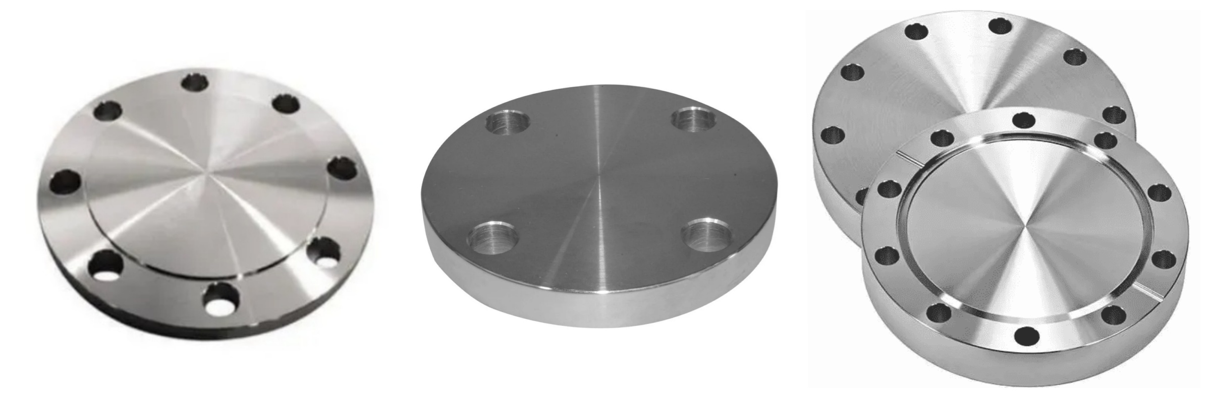
Raised Face (RF Type)
The most common sealing face type. The sealing surface is raised above the bolt circle face, making gasket installation easy. Suitable for pressure classes Class 150 to Class 2500 (PN 10 to PN 420) and compatible with various gaskets.
Flat Face (FF Type)
The sealing surface is flush with the entire flange face. Commonly used with cast iron flanges or for mating with cast iron valves. Suitable for low-pressure applications such as water, air, and other non-corrosive media under Class 125/150.
Male and Female Face (MFM Type)
Uses a pair of male and female flanges. This design effectively prevents the gasket from being blown out. Suitable for high-pressure, flammable, explosive, or highly toxic media, with pressure ratings up to Class 2500 (PN 420).
Tongue and Groove Face (TG Type)
Uses a pair of tongue and groove flanges. The gasket is placed inside the groove, protecting it from media flow and providing excellent sealing performance. Suitable for high-pressure, vacuum, or applications requiring tight seals, such as ammonia synthesis or urea plants.
Ring Type Joint Face (RTJ Type)
The sealing surface is machined with a trapezoidal ring groove. It uses a metal ring gasket, creating a seal through initial contact stress. Suitable for high-temperature and high-pressure applications such as high-pressure steam or refinery hydrogenation units, with pressure ratings up to Class 2500 (PN 420) and above.
TYPE A: Flat Face (FF)
The sealing surface is a smooth, flat plane. Suitable for low-pressure, non-flammable, non-explosive, and non-toxic media applications. Simple structure and low installation cost.
TYPE B: Raised Face (RF)
The sealing surface is slightly raised above the flange face. It is the most widely used type in industrial applications due to its simple structure and easy installation. Suitable for medium and low-pressure conditions.
TYPE C: Tongue
This is the raised part of the "Tongue and Groove" pair. Must be used together with TYPE D (Groove).
TYPE D: Groove
This is the recessed part of the "Tongue and Groove" pair. Must be used together with TYPE C (Tongue).
TYPE E: Spigot
This is the raised part of the "Male and Female" face pair. Must be used together with TYPE F (Recess).
TYPE F: Recess
This is the recessed part of the "Male and Female" face pair. Must be used together with TYPE E (Spigot).
TYPE G: O-ring Spigot
Features a raised boss specifically designed to accommodate an O-ring seal. Must be used with TYPE H (O-ring Groove) or a matching flat face to achieve metal-to-metal contact combined with O-ring sealing.
TYPE H: O-ring Groove
Features a groove specifically designed to accommodate an O-ring seal. Must be used together with TYPE G (O-ring Spigot).
In the American system, fasteners used with ASME flanges should have bolts meeting ASTM A193 and nuts meeting ASTM A194 standards. Dimensions should comply with ASME B18.2.1 and B18.2.2.
EN 1515-2:2001: Flanges and their joints – Bolting – Part 2: Classification of bolt materials for steel flanges (PN designated).
EN 1515-4:2009: Flanges and their joints – Bolting – Part 4: Selection of bolting for equipment subject to the Pressure Equipment Directive 97/23/EC.
ASME B16.20: Specifies the dimensions, materials, and testing requirements for metallic gaskets, spiral-wound gaskets, and jacketed gaskets for pipe flanges, ensuring they match the sealing faces of ASME B16.5 and B16.47 flanges.
EN 1514-1:1997: Dimensions of gaskets for PN-designated flanges – Part 1: Non-metallic flat gaskets with or without inserts.
EN 1514-2:2014: Gaskets for PN-designated flanges – Part 2: Spiral wound gaskets for steel flanges.
Preparation: Check the blind flange sealing face for scratches or damage. Confirm that the size and pressure rating match the piping system.
Gasket Installation: Select a gasket that meets the media characteristics and pressure requirements. Place it centered on the sealing face.
Bolt Tightening: Tighten bolts in a staggered, cross-pattern sequence in multiple steps. Use the specified torque value to avoid uneven tightening leading to seal failure.
Regularly check the sealing face for corrosion.
Blind flanges in long-term service should undergo periodic pressure leak testing.
After disassembly, inspect the sealing face. Repair or replace it if damaged.
Steel flanges and blind flanges are widely used in:
Petrochemical Industry: Refinery units, chemical plant piping systems handling high-pressure, high-temperature, corrosive media.
Power Industry: Steam pipes and feedwater systems in thermal and nuclear power plants.
Shipbuilding: Marine piping systems, complying with standards such as GB/T 4450-2008 for marine blind steel flanges.
Municipal Engineering: Valve connections and end sealing in water supply and heating pipelines.
Pharmaceutical & Food Industry: Sanitary stainless steel flange systems meeting cleanliness requirements.
